High-precision current sampling circuit without operational amplifier for low voltage power supply

A current sampling, low voltage technology, applied in the direction of logic circuit coupling/interface using field effect transistors, measuring current/voltage, logic circuit connection/interface layout, etc., can solve multiple noise and errors, limit circuit response performance, sampling The accuracy is limited by the size of the output current of the current tube, so as to reduce the sampling error, avoid the design complexity, and reduce the stacking effect.

Inactive Publication Date: 2011-04-20
NAT UNIV OF DEFENSE TECH
View PDF0 Cites 0 Cited by
  • Summary
  • Abstract
  • Description
  • Claims
  • Application Information

AI Technical Summary

Problems solved by technology

However, the shortcomings of this circuit are also more obvious
First of all, equations (1) and (2) are still valid for this circuit, so the sampling accuracy is also limited by the output current of the current tube; in addition, due to the control of the current switching signal of the sampling main circuit, in each sampling period, The main circuit will go through a process from cut-off to turn-on, which will undoubtedly introduce more noise and errors, and greatly limit the response performance of the circuit

Method used


Image

  • High-precision current sampling circuit without operational amplifier for low voltage power supply
  • High-precision current sampling circuit without operational amplifier for low voltage power supply
  • High-precision current sampling circuit without operational amplifier for low voltage power supply

Examples


Embodiment Construction

[0036] The structure and working process of the current sampling circuit with no operational amplifier structure suitable for low-voltage power supply disclosed by the present invention will be described in detail below in conjunction with the accompanying drawings.

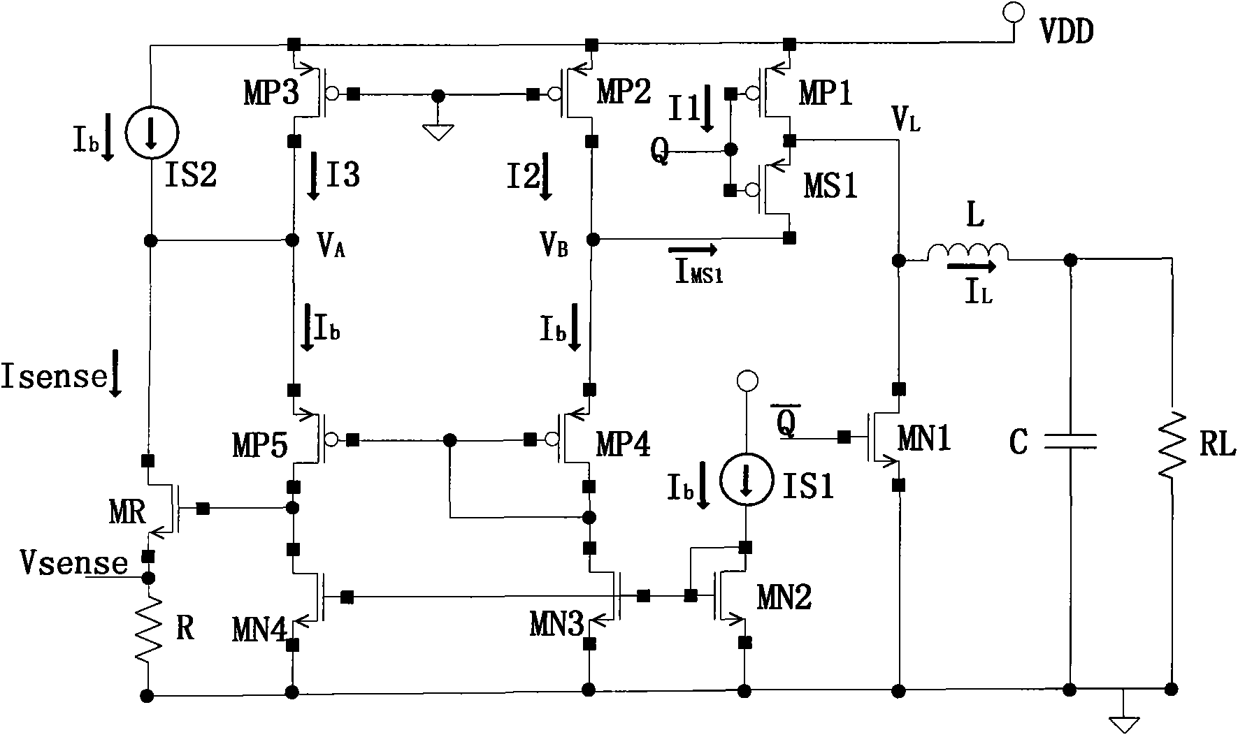
[0037] image 3 Shown is the current sampling circuit without operational amplifier structure suitable for low-voltage power supply disclosed by the present invention.

[0038]The main current is composed of a cascaded current mirror structure, the tail current path formed by MN3 tube and MN4 tube, the source is grounded, the gate is connected in parallel, and connected to the gate and drain of the MN2 tube in the basic bias circuit at the same time, the mirror image comes from The current of the MN2 tube in the bias circuit; the MP4 tube and the MP5 tube form a self-bias circuit and form a current mirror structure, where the gate and drain of the MP4 tube are connected, and connected to the grid of the MP5 tube ...


PUM


Abstract

Current sampling circuits are widely applied in various integrated circuits taking current as a medium; along with the continuous improvement of the technical level of the integrated circuit, power supply voltage continuously lowers, and traditional current sampling structure is not suitable for application of integrated circuit for low voltage power supply. The invention discloses a high-precision current sampling circuit for switch power source control loops, adopts a current mirror structure to replace an operational amplifier, simplifies circuit structure, utilizes microampere-level fixedbias to improve the response speed of the current sampling circuit, and actively corrects sampling errors led in by the fixed bias and improves sampling precision. The circuit is composed of a main body structure, basic bias, current-voltage sampling output, fixed bias compensation, a current tube and sampling switch and an external load.

Description

technical field [0001] The invention belongs to the field of integrated circuit design and is used for accurately sampling the current passing through a transistor, in particular to a high-precision current sampling circuit suitable for low-voltage power supply occasions, which does not require an operational amplifier and has a simple structure. Background technique [0002] Current sampling technology is the key technology in current mode control loop and current protection circuit. In integrated circuits that use current to form closed-loop control, current sampling is an essential circuit component, especially in switching power supplies that are controlled by current feedback. In an integrated circuit, the performance of the current sampling circuit is directly related to the overall performance of the circuit. [0003] The most common method of current sampling is to directly connect a small-value sampling resistor in series with the sampled current path, and obtain th...

Claims


Application Information

Patent Timeline
Patent Type & Authority Patents(China)
IPC IPC(8): G01R19/00H03K19/0185G05F3/26
Inventor 马卓张民选赵振宇李少青陈吉华陈怒兴郭阳王浩
Owner NAT UNIV OF DEFENSE TECH
Why Eureka
Try Eureka