
Control method and system of virtual synchronous inverter

A technology of virtual synchronization and control method, which is applied in the direction of single-network parallel feeding arrangement, etc., can solve the problems of power distribution and frequency adjustment, deterioration of power, and impact on system stability, so as to improve system stability and avoid large amount of calculation , Avoid designing complex effects

Inactive Publication Date: 2020-01-07
CHINA ELECTRIC POWER RES INST +2
View PDF3 Cites 0 Cited by
  • Summary
  • Abstract
  • Description
  • Claims
  • Application Information

AI Technical Summary

Problems solved by technology

However, the inverter does not have the rotating rotor structure of a synchronous machine so that it cannot run completely like a synchronous machine, so the PLL link is required to detect the grid frequency
This method needs to obtain grid-connected voltage information, and is not suitable for weak grids or severe grid distortions. At this time, the PLL link will affect the stability of the system.
Another method is to use the grid frequency obtained by substituting the grid nominal frequency for the PLL link. The resulting damping power will be obtained by multiplying the difference between the rotor rotation angular frequency and the grid nominal frequency by the damping coefficient. and frequency regulation have an effect on
In addition, since the line impedance of the microgrid system is usually resistive or resistive, there is a certain coupling between active and reactive power regulation based on droop control, which affects the stability and dynamic performance of the system.
The traditional power decoupling control is to compensate the line voltage drop by introducing a virtual impedance. The realization method of the virtual impedance is to introduce a differential term through a low-pass filter to suppress high-frequency interference. The differential term will affect the performance of the virtual impedance and even worsen the power Accuracy of dynamic response and power distribution

Method used


Image

  • Control method and system of virtual synchronous inverter
  • Control method and system of virtual synchronous inverter
  • Control method and system of virtual synchronous inverter

Examples


Embodiment Construction

[0062] In order to better understand the present invention, the content of the present invention will be further described below in conjunction with the accompanying drawings and examples.

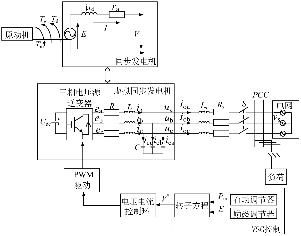
[0063] The technical problem to be solved by the present invention is to realize the decoupling control of inverter output active and reactive power by proposing a virtual synchronous inverter technology based on improved power decoupling control applied to The rotor equation of the synchronous machine saves the phase-locked (PLL) link, and eliminates the influence of the constant damping coefficient on the droop control.

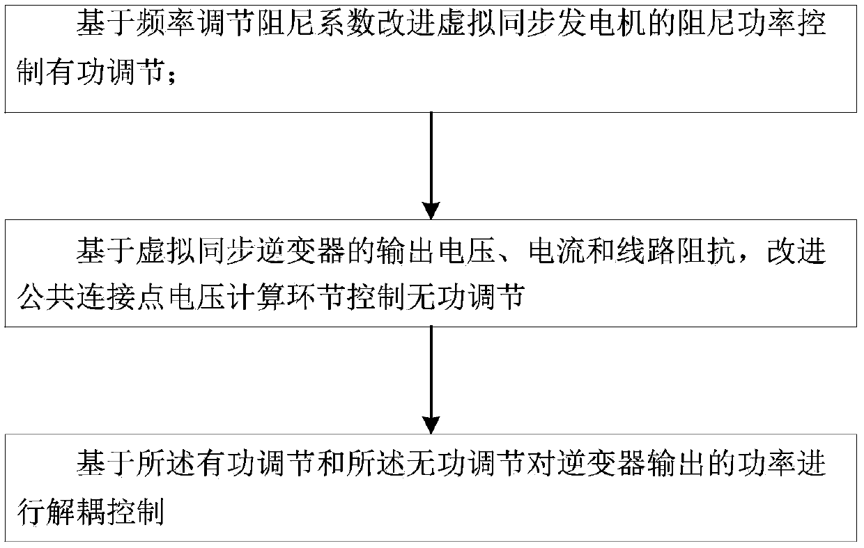
[0064] from figure 1 It can be seen that a control method for a virtual synchronous inverter includes:

[0065] Improving active power regulation for virtual synchronous generator control based on frequency-adjusted damping coefficient.

[0066] Further, the damping power control active power adjustment of the virtual synchronous generator is improved based on the fre...


PUM


Abstract

The invention discloses a control method and system of a virtual synchronous inverter. The control method comprises the steps: improving damping power of a virtual synchronous generator to control active adjustment based on a frequency adjustment damping coefficient; based on the output voltage, current and line impedance of the virtual synchronous inverter, improving a common connection point voltage calculation link to control reactive power regulation; and performing decoupling control on the power output by the inverter based on the active adjustment and the reactive adjustment. Accordingto the technical scheme, decoupling control over active power and reactive power output by the inverter is achieved, a synchronous phase lock (PLL) link is omitted by improving a rotor equation of thevirtual synchronous machine, and the influence on droop control due to the fact that a constant damping coefficient is adopted is eliminated.

Description

technical field [0001] The invention belongs to the field of new energy power generation, and in particular relates to a control method and system for a virtual synchronous inverter. Background technique [0002] Renewable energy sources such as photovoltaics and wind energy are considered to be a reliable solution to the energy crisis and environmental pollution, and microgrid technology is an important form of increasing the penetration rate of renewable energy. Since solar and wind energy are greatly affected by the environment, and their output is unstable and discontinuous, new energy power generation systems usually require power electronic conversion devices to feed electric energy to the AC bus. Traditional grid-connected inverter control strategies do not consider the problem of excessive frequency change rate caused by the lack of inertia. Therefore, scholars have proposed a virtual synchronous generator control method that can simulate the operating characteristi...

Claims


Application Information

Patent Timeline
Patent Type & Authority Applications(China)
IPC IPC(8): H02J3/48H02J3/50
CPCH02J3/48H02J3/50
Inventor 董瑞彪李国华阴昌华陈志彬刘永笑金阳药炜杨晟孙瑾张翔任健铭闫志乾李晓霞王萍蒋红音吴鸣宋振浩郑楠吕志鹏
Owner CHINA ELECTRIC POWER RES INST
Learn More