Cavity medium filter

A dielectric filter and cavity technology, used in waveguide-type devices, circuits, electrical components, etc., can solve the problems of unfavorable device performance optimization, limited tuning effect, and increased volume, and achieve excellent performance indicators and obvious adjustment effects. Effect

Active Publication Date: 2010-01-20
COMBA TELECOM TECH (GUANGZHOU) CO LTD +1
View PDF0 Cites 21 Cited by
  • Summary
  • Abstract
  • Description
  • Claims
  • Application Information

AI Technical Summary

Problems solved by technology

Due to its own loss, the traditional metal coaxial cavity filter cannot obtain a high quality factor (Q value) when the cavity size is limited, resulting in certain restrictions on indicators such as out-of-band rejection and insertion loss. , and the metal surface silver plating treatment and other links will also have a certain impact on the passive intermodulation index
[0003] As for the existing cavity dielectric filter, since there is no suitable and convenient tuning method at present, it is difficult to debug the device during the manufacturing process, and the RF performance index of the device is also difficult to achieve.
[0004] In the known cavity dielectric filter, two methods are mainly used for tuning, one is to tune by setting a plurality of vertical tuning rods deep inside the cavity on the filter cover plate, and the other is to tune by setting a plurality of vertical tuning rods on the filter side Multiple tuning rods are inserted horizontally on the wall for tuning. The tuning effects of these two methods are very limited, and the filter is basically used as an overall unit for overall tuning.
[0005] In addition, most of the existing cavity dielectric filters suppress out-of-band signals through the natural attenuation of the coaxial dielectric resonator itself, and this method achieves higher out-of-band suppression by increasing the number of coaxial dielectric resonators , will lead to an increase in volume and cost, and is not conducive to the performance optimization of the device

Method used


Image

  • Cavity medium filter
  • Cavity medium filter
  • Cavity medium filter

Examples


Embodiment Construction

[0025] Below in conjunction with accompanying drawing and embodiment the present invention will be further described:

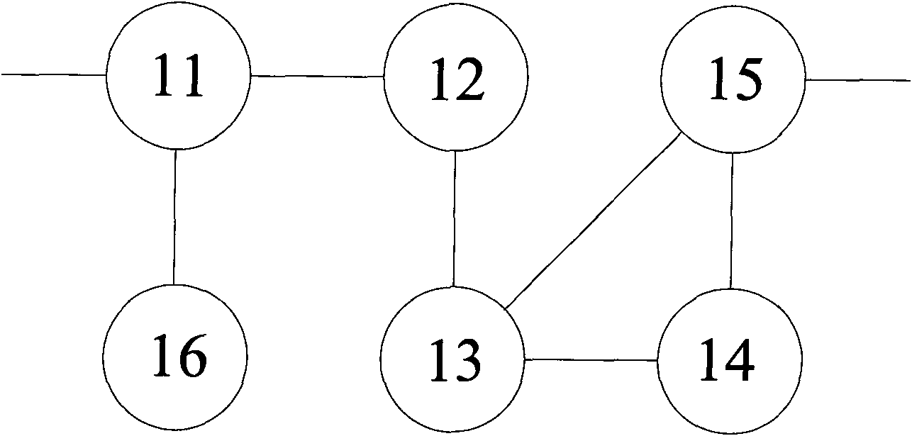
[0026] see figure 1 , the cavity dielectric filter of the first embodiment of the present invention according to figure 1 The electrical structure distribution, in which the coupling order of the signal acts between several resonant cavities 11 to 16, the resonant cavity 11 and the resonant cavity 15 are used as the connection end, the radio frequency signal is input from the resonant cavity 11 and output from the resonant cavity 15, or vice versa 15 input and output from resonant cavity 11. Taking the former as an example, after the signal is coupled from the resonant cavity 11 to the resonant cavity 12 and then to the resonant cavity 13, the resonant cavities 13, 14, and 15 form a cross-coupling relationship, and are output only after cross-coupling. In addition, the resonant cavity 16 is used as the null cavity 16 to reflect with the resonant cavity 11, ...


PUM


Abstract

The invention discloses a cavity medium filter comprising a cavity provided with a plurality of resonant cavities. Each resonant cavity is provided with a resonator, parts of resonant cavities form cross coupling, and a coupling window is arranged between at least one pair of resonant cavities; in addition, at least one coupling window is provided with a tuning device which is used for matching and adjusting the coupling amount of belonged adjacent two resonant cavities on at least two places of the coupling window; one of the resonant cavities serves as a zero cavity and generates reflectionwith the other resonant cavity to generate transmission zero on the side of a frequency band; and a cross coupling device for generating transmission zero on the other side of the frequency band is arranged between two resonant cavities used for cross coupling. The invention ensures that the cavity medium filter can accurately tune and improve the out-of-band inhibition capability thereof, so that the integral performance of the filter is comprehensively improved.

Description

【Technical field】 [0001] The invention relates to the field of mobile communication equipment, in particular to a cavity dielectric filter. 【technical background】 [0002] In modern mobile communication technology, microwave radio frequency devices have become an indispensable and important part. As a basic radio frequency device, the filter has a series of indicators such as insertion loss, out-of-band rejection, passive intermodulation and power capacity, which have an important impact on the performance of the whole machine. Due to its own loss, the traditional metal coaxial cavity filter cannot obtain a high quality factor (Q value) when the cavity size is limited, resulting in certain restrictions on indicators such as out-of-band rejection and insertion loss. , and the metal surface silver plating treatment and other links will also have a certain impact on the passive intermodulation index. [0003] As for the existing cavity dielectric filter, since there is no sui...

Claims


Application Information

Patent Timeline
Patent Type & Authority Applications(China)
IPC IPC(8): H01P1/208
Inventor 丁海黄景民邸英杰贺斌
Owner COMBA TELECOM TECH (GUANGZHOU) CO LTD
Why Eureka
Try Eureka