Control circuit used for single-induction and multi-output system

A multi-channel output and control circuit technology, which is applied in the direction of output power conversion devices, control/regulation systems, electrical components, etc., can solve problems such as increased costs, poor system performance, and complicated control methods, and achieves control and reduction. The effect of small output voltage ripple and optimized system performance

Active Publication Date: 2010-01-20
CHENGDU MONOLITHIC POWER SYST
View PDF2 Cites 8 Cited by
  • Summary
  • Abstract
  • Description
  • Claims
  • Application Information

AI Technical Summary

Problems solved by technology

This control method tends to cause large ripples in other outputs due to no energy supply for several consecutive cycles, making the system performance worse
[0003] In addition, some single-inductor multiple output conversion technologies use digital control, which is very complicated and increases the cost.

Method used


Image

  • Control circuit used for single-induction and multi-output system
  • Control circuit used for single-induction and multi-output system
  • Control circuit used for single-induction and multi-output system

Examples


Embodiment Construction

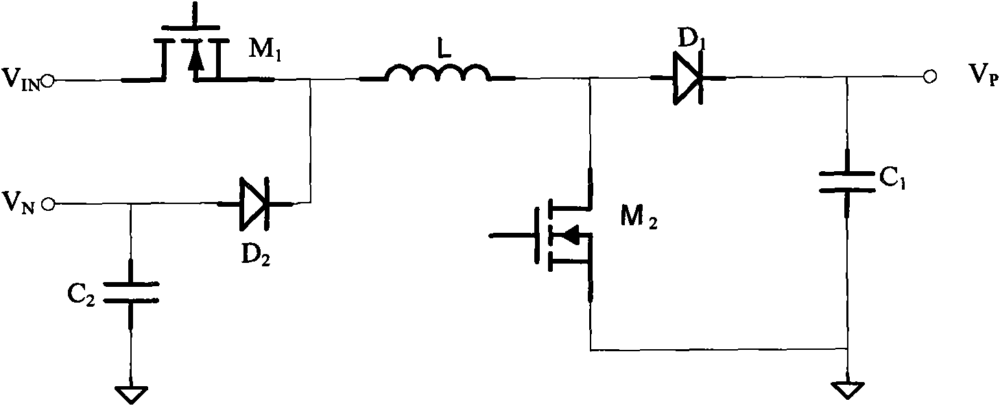
[0021] figure 1 It is the main circuit diagram of a typical single inductor two output system. Such as figure 1 As shown, the main circuit includes the input V IN , Output V P and V N , inductance L, capacitance C 1 、C 2 , switching device M 1 , M 2 , and the diode D 1 、D 2 . input V IN connected to the switching device M 1 the drain of the switching device M 1 The source is connected to one end of the inductor L and the diode D 2 The cathode of the inductor L is connected to the diode D 1 The anode and switching device M 2 the drain of the diode D 1 The cathode is connected to the output V P , Diode D 2 The anode of the is connected to the output V N , switching device M 2 The source of the switching device M 1 and M 2 The gate of is connected to the control circuit, which will be explained in detail when introducing Figure 4 later. at the output V P A capacitor C is connected across the 1 , at the output V N A capacitor C is connected across the 2 ...


PUM


Abstract

The invention provides a control circuit used for controlling a single-induction and multi-output system. The control circuit adopts a first control loop to realize control on a current peak mode of the system, and adopts an algebraic relation of various outputs of the system for a second control loop to control the duty ratio of each switching device of a main circuit of the system so as to realize the control on each output voltage of the system, reduce the ripple wave of each output voltage and optimize the performance of the system.

Description

technical field [0001] The present invention relates to a power converter, and more specifically, the present invention relates to a circuit for a single-inductance multi-output power converter. Background technique [0002] Switching power supply circuits have been well applied in many fields. Three of the circuit topologies are the most common: buck, boost, and buck-boost. When the application requires multiple outputs, the single-inductor multiple-output power converter technology is widely used because only one inductor is used, which improves the circuit cost and circuit size. Existing single-inductor multiple-output converter technologies often use "priority" for control. The so-called priority means that when the system detects that the output voltage of a certain channel has dropped relatively low, it will turn off the corresponding switching devices of other outputs in the next several cycles, and compensate the output voltage of this channel alone. This control ...

Claims


Application Information

Patent Timeline
IPC IPC(8): H02M1/08G05F1/10
Inventor 邝乃兴杜磊张军明任远程
Owner CHENGDU MONOLITHIC POWER SYST
Why Eureka
Try Eureka