Inverter generator

A technology of inverters and generators, which is used in the control of generators, machines/engines, and the control of generators through magnetic field changes. Effect

Inactive Publication Date: 2010-01-27
HONDA MOTOR CO LTD
View PDF1 Cites 6 Cited by
  • Summary
  • Abstract
  • Description
  • Claims
  • Application Information

AI Technical Summary

Problems solved by technology

However, the ignition control circuit is usually an analog circuit and is controlled by a simple method such as constant setting. Therefore, when the engine speed decreases with the ignition being stopped, the ignition is restarted and the over-rotation becomes again. The engine keeps repeating over-rotation, ignition stop, RPM increase, over-rotation, ignition stop, ..., so that the over-rotation state cannot be stopped

Method used


Image

  • Inverter generator
  • Inverter generator
  • Inverter generator

Examples


Embodiment Construction

[0017] Hereinafter, the best mode for implementing the inverter generator according to the present invention will be described with reference to the drawings.

[0018] 【Example】

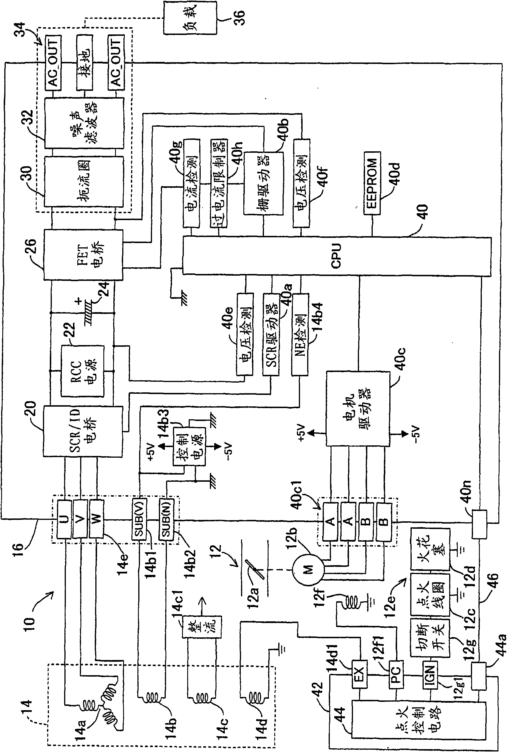
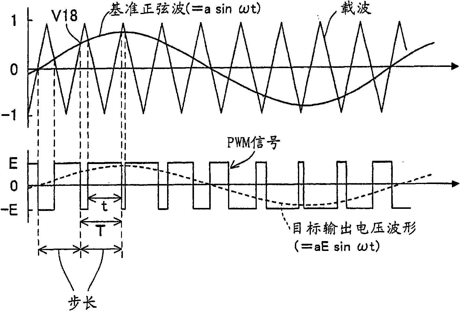
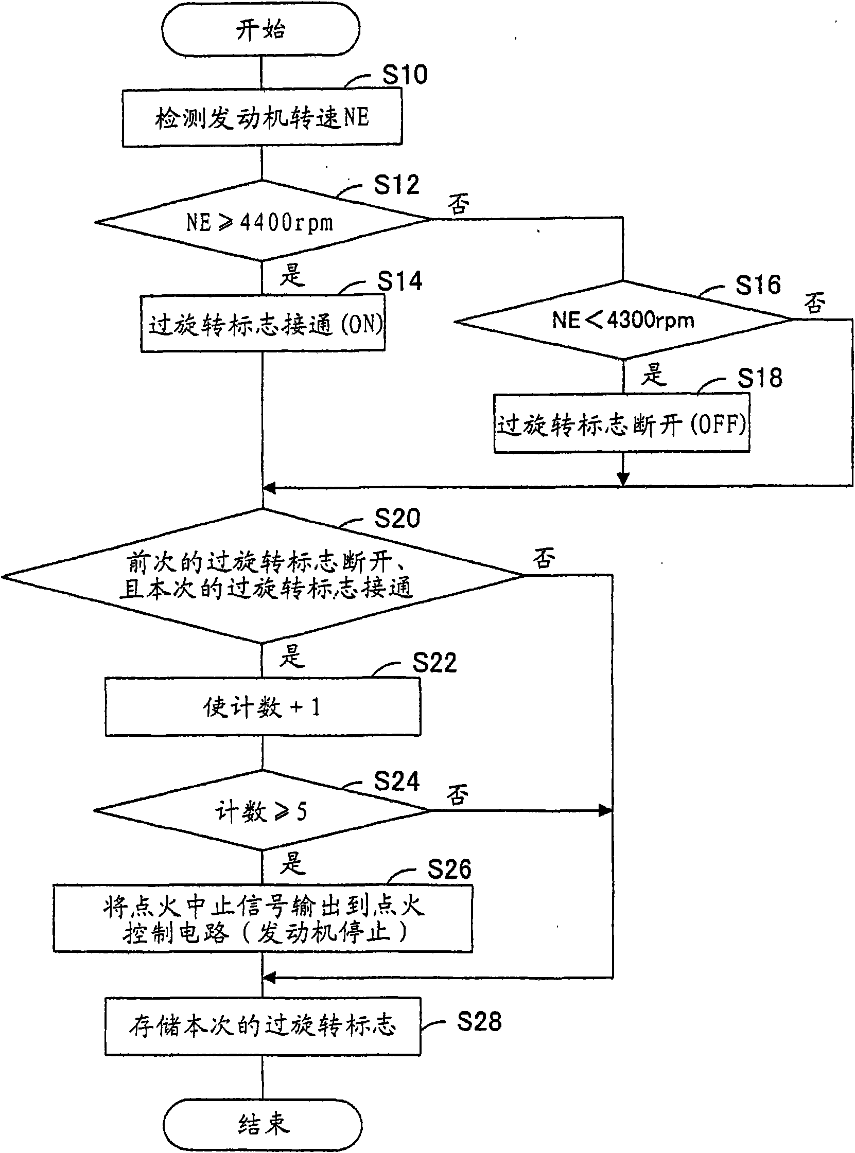
[0019] figure 1 It is a block diagram generally showing the inverter generator according to the embodiment of the present invention.

[0020] exist figure 1 In , reference numeral 10 denotes an inverter generator, and the generator 10 has a motor (internal combustion engine) 12 and has a rated output of about 3 kW (AC 100V, 30A). Engine 12 is an air-cooled engine and is a spark ignition type. Its throttle valve 12a utilizes a throttle motor (actuator) 12b made of a stepper motor to open and close, and utilizes a recoil starter (not shown) to open and close. start.

[0021] A circular stator (not shown) is fixed near the cylinder head of the engine 12, and a three-phase output winding (main phase) consisting of U phase, V phase, and W phase constituting the engine power generation unit 14 is wound...


PUM


Abstract

In an inverter generator having a generator unit driven by an internal combustion engine, an inverter that inverts converted direct current to alternating current with switching elements to supply to an electrical load, an inverter driver that comprises an microcomputer and drives the switching elements with a PWM signal to make the alternating current of a predetermined frequency, an ignition unit that ignites the engine, and an ignition controller that controls operation of the ignition unit, the engine speed is detected (S10) and it is determined whether the engine is under over revolutioncondition based on the detected engine speed (S12 to S26). The inverter driver sends a command to the ignition controller to terminate the ignition to stop the engine, when the engine is under the over revolution condition (S26), thereby enabling to prevent the engine from experiencing over revolution repeatedly.

Description

technical field [0001] The present invention relates to an inverter generator, and more specifically relates to an inverter generator that has a power generation unit driven by an engine and reliably prevents over-rotation of the engine. Background technique [0002] Such an inverter type generator is well known, that is, temporarily converts the AC power output from the power generating unit driven by the engine into DC power, and generates a PWM signal based on a reference sine wave and a carrier wave using a target output voltage waveform The switching element is driven to convert the DC power into an AC power of a predetermined frequency (commercial frequency) and output it. As an example of this inverter generator, the technology described in the following Patent Document 1 can be cited. [0003] Patent Document 1: Japanese Patent Application Laid-Open No. 4-355672 [0004] In the inverter generator described in Patent Document 1, the engine rotation speed is usually d...

Claims


Application Information

Patent Timeline
Patent Type & Authority Applications(China)
IPC IPC(8): F02D41/22
CPCF02P9/005H02P9/04H02P9/30
Inventor 桥本省二室野井和文
Owner HONDA MOTOR CO LTD
Why Eureka
Try Eureka