
Position measuring device and position measuring method

A measurement device and measurement method technology, applied in the direction of measurement device, optical device, instrument, etc., can solve the problems of low measurement sensitivity and complex overall structure of the measurement system, and achieve the effects of simple structure, reduced impact, and improved sensitivity

Inactive Publication Date: 2010-01-27
SHANGHAI MICRO ELECTRONICS EQUIP (GRP) CO LTD
View PDF5 Cites 16 Cited by
  • Summary
  • Abstract
  • Description
  • Claims
  • Application Information

AI Technical Summary

Problems solved by technology

[0005] Another example is the focusing and leveling measurement system in a lithography machine in a published patent (patent number: CN20071017196.5), which is another application of the object position measurement system, although the method provided by this patent is relatively The stability of the method has been improved, but in this patent, there are still the following disadvantages: the projection and detection grating adopts a coded grating detection scheme, which leads to a complex overall structure; in addition, because the method does not use the corresponding subdivision technology, Therefore, the measurement sensitivity of the measurement system is not high

Method used


Image

  • Position measuring device and position measuring method
  • Position measuring device and position measuring method
  • Position measuring device and position measuring method

Examples


Embodiment Construction

[0030] Hereinafter, the present invention will be further described with reference to the accompanying drawings.

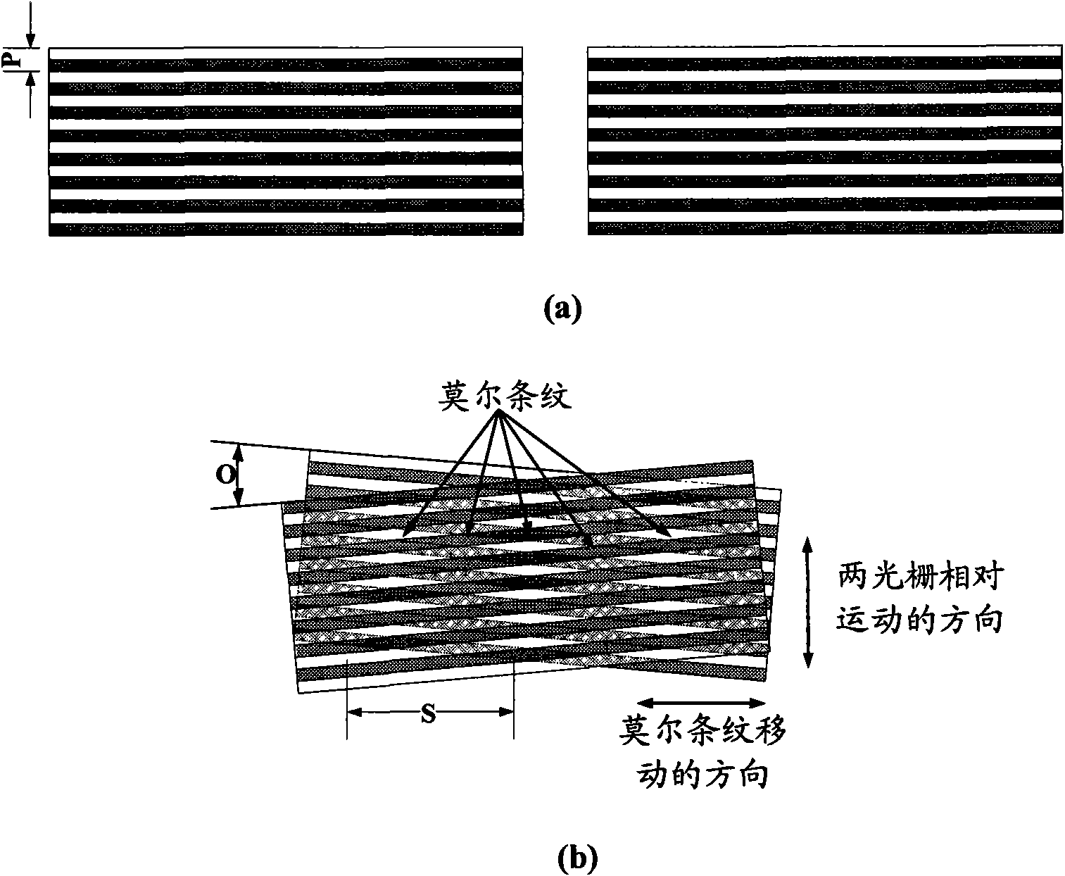
[0031] Since the position measuring device and method of the present invention are designed based on the principle of Moiré fringe detection, before introducing the position measuring device and method of the present invention, the formation and characteristics of the moiré fringes will be introduced first. figure 1 A schematic diagram of the formation of Moiré fringes is shown. in, figure 1 (a) shows the amplitude grating when the two periods are P, figure 1 (b) shows figure 1 Two amplitude gratings with period P in (a) are superimposed at a certain angle (such as o) and illuminated to form moire fringes with period S. When the angle o between the two amplitude gratings with period P is small, the following relationship is satisfied between the period P of the amplitude grating and the period S of the moiré fringes formed by it:

[0032] S=P / o (1)

[0033] T...


PUM


Abstract

The invention provides a position measuring device and a position measuring method. The position measuring device comprises a light source module, an illumination module, a projection aperture, a projection raster, a projection imaging module, a detection imaging module, a detection raster and a detection module, wherein after light emitted by the light source module passes through the illumination module, the projection aperture and the projection raster, the projection raster is imaged on an object to be measured by the projection imaging module so as to form a raster image; and the raster image is imaged to the detection raster so as to form a detection image by the detection imaging module; the detection image and the detection raster are overlaid to form a Moire fringe; the Moire fringe is detected by the detection module; and the projection raster is a rough raster. The invention has simple structure and higher sensitivity and measures in a direct way.

Description

technical field [0001] The invention relates to an opto-mechanical device, in particular to a position measuring device and method. Background technique [0002] The lithography apparatus is one of the important equipments for the production of large-scale integrated circuits. The lithography machine can transfer the pattern on the mask to the object to be processed (such as silicon wafer, etc.) in a certain proportion through the exposure device. Silicon wafer here refers to all exposed objects, including substrates, coatings and photoresists. During the exposure process, it is necessary to keep the corresponding surface of the processing object (such as a silicon wafer, etc.) within the focal depth range of the exposure device. To this end, the lithography machine adopts a focusing and leveling measurement system for measuring the surface position information of the processed object (such as a silicon wafer, etc.). The focusing and leveling measurement system can work t...

Claims


Application Information

Patent Timeline
IPC IPC(8): G01B11/00G01B11/02G01B11/26
Inventor 张冲李志丹
Owner SHANGHAI MICRO ELECTRONICS EQUIP (GRP) CO LTD
Learn More