Detection and predetermination calculational method for rapid variation light power

An optical power and fast technology, applied in the direction of using electrical radiation detectors for photometry, etc., can solve the problems of narrow TIA circuit bandwidth, large circuit gain, ignoring optical power detection, etc., to suppress gain overshoot or undershoot. , The speed of calculation output is fast, and the effect of good application prospects

Active Publication Date: 2010-01-27
GUANGXUN SCI & TECH WUHAN
View PDF0 Cites 10 Cited by
  • Summary
  • Abstract
  • Description
  • Claims
  • Application Information

AI Technical Summary

Problems solved by technology

[0004] The first one is that when the gain-bandwidth product of the operational amplifier is constant, the lower the input optical power, the greater the transresistance of the TIA circuit position, the greater the circuit gain, and the narrower the bandwidth of the TIA circuit , the rapidly changing input optical signal will produce distortion when passing through the TIA circuit, and the greater the transimpedance, the more serious the distortion
The current method is to judge whether the optical power changes rapidly by comparing whether the output signal of the TIA circuit exceeds the threshold, but it is impossible to accurately calculate the actual value of the rapidly changing optical power based on the distorted sig

Method used


Image

  • Detection and predetermination calculational method for rapid variation light power
  • Detection and predetermination calculational method for rapid variation light power
  • Detection and predetermination calculational method for rapid variation light power

Examples


Embodiment Construction

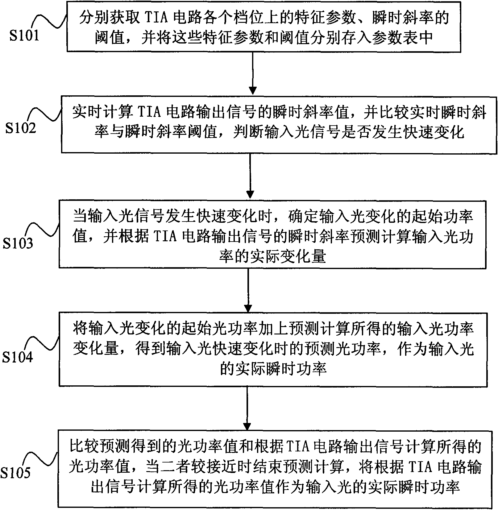
[0039] The method for detecting and predicting calculation of rapidly changing optical power of the present invention will be described in detail below in conjunction with the embodiments and drawings, but the description of the implementation mode here does not limit the present invention.

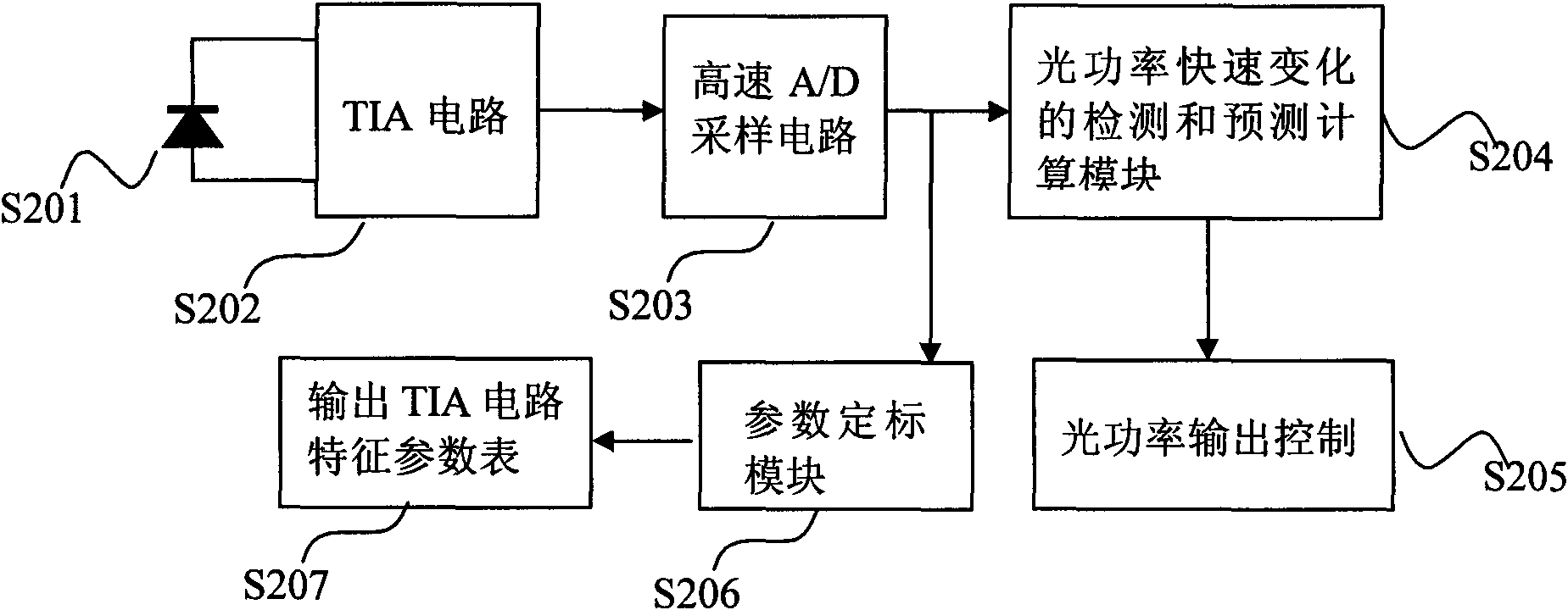
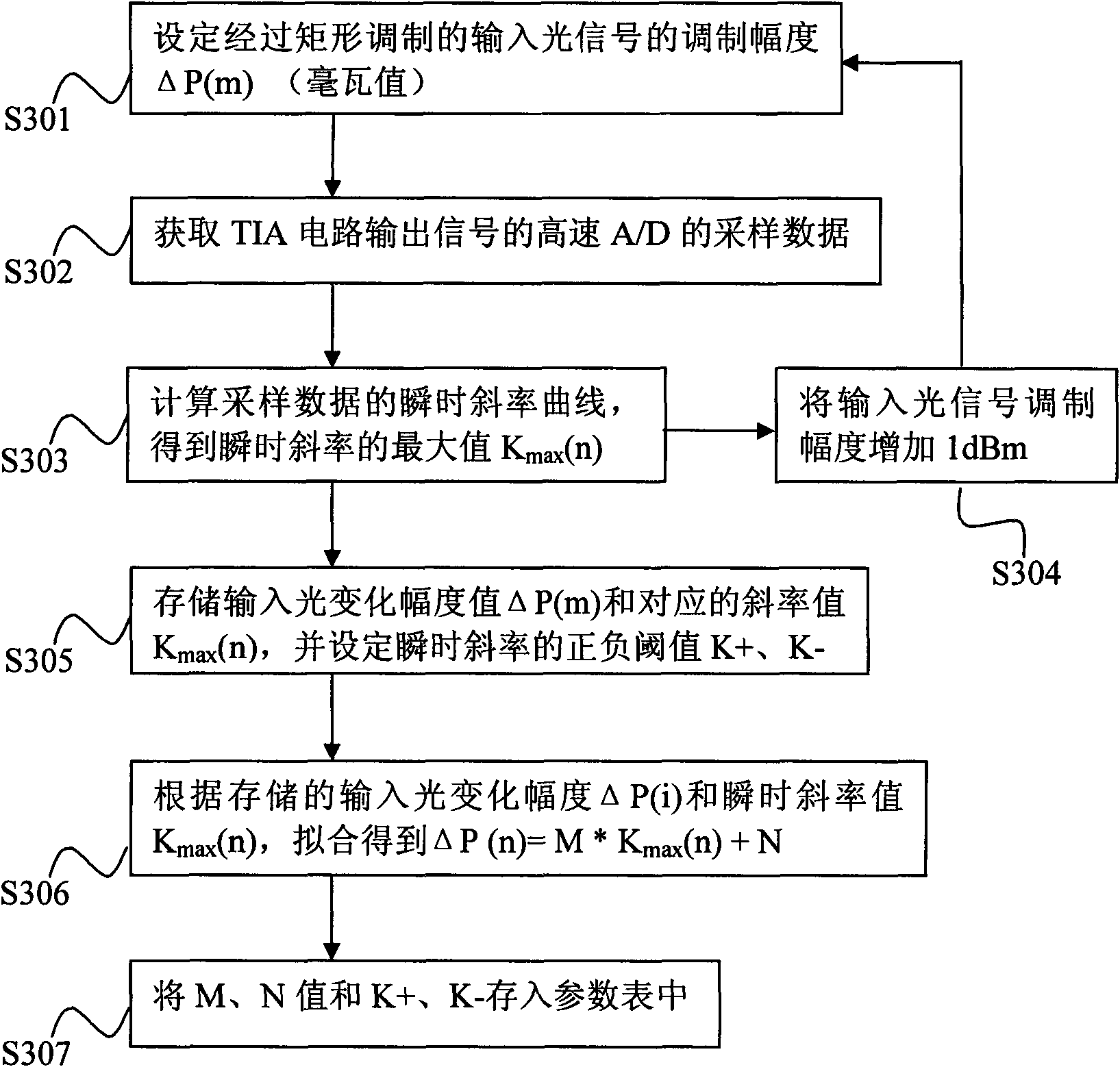
[0040] Due to the characteristics of the present invention, the optical power detection and prediction calculation methods of the multi-gear TIA circuit and the single-gear TIA circuit are exactly the same, therefore, for the convenience of understanding the present invention, except for the EDFA (erbium-doped fiber amplifier) ​​application example, the rest of the implementation The method and the illustrations of the rapidly changing optical power detection and prediction calculation methods in the drawings all omit the gear switching control operation.

[0041] Such as figure 1 As shown, the method for detecting and predicting calculation of fast-changing optical power of the present i...


PUM


Abstract

A detection and predetermination calculational method for rapid variation light power comprises steps of: respectively obtaining characteristic parameters and a threshold value of an instant slope ratio of all gears of a TIA circuit which are stored in a parameter table; calculating the instant slope ratio value of output signals of the TIA circuit in real time, and comparing the real time instant slope ratio value and the threshold value of instant slope ratio; when input light signal varies quickly, determining the beginning power value of input light variation, and calculating the real variable quantity of the input light power according to the instant slope ratio of the output signals of the TIA circuit; adding the beginning light power of input light variation and input light power variable quantity obtained by predetermination calculation to obtain determination light power when input light rapid varies to serve as the real instant power of the input light, comparing the light power value obtained by predetermination and the light power value obtained according to the output signals of the TIA circuit, finishing the predetermination calculation when the predetermined light power value and the light power value are closer, using the light power value as the real instant power of the input light. The method greatly speeds up light power detection speed and can accurately display the light power value of fast variation.

Description

technical field [0001] The invention relates to detection and prediction calculation of optical power. In particular, it relates to a method for detecting and predicting calculation of fast-changing optical power that can accurately predict and calculate the changing target power at the instant when the input light changes rapidly. Background technique [0002] In optical communication systems, there are generally two types of optical power detection circuits: one is a transconductance amplifier circuit composed of a logarithmic operational amplifier. The advantage of this circuit is that it has a wide dynamic range. The detection sensitivity of variable signals is low, which is not conducive to the detection of rapidly changing optical power; the other is a TIA (Transimpedance Amplifier, transimpedance amplification) circuit using a linear operational amplifier. The output of the TIA circuit is in a linear relationship. It is easier to detect the rapid change of the input ...

Claims


Application Information

Patent Timeline
IPC IPC(8): G01J1/42
Inventor 简敬元张翠红印新达
Owner GUANGXUN SCI & TECH WUHAN
Why Eureka
Try Eureka