Phase measurement device of beam splitter

A technology of phase measurement and beam splitter, applied in measurement devices, measurement optics, optical radiation measurement, etc., can solve problems such as not found, and achieve the effect of simple measurement and easy operation

Inactive Publication Date: 2010-01-27
SHANGHAI INST OF OPTICS & FINE MECHANICS CHINESE ACAD OF SCI
View PDF0 Cites 10 Cited by
  • Summary
  • Abstract
  • Description
  • Claims
  • Application Information

AI Technical Summary

Problems solved by technology

For this kind of beam splitting device, almost all devices only measure the splitting ratio, that is, the light intensity energy ratio of the two split beams, and do not measure the phase change relationship of the beam after passing through the splitting device, but in some applications , such as spatial

Method used


Image

  • Phase measurement device of beam splitter
  • Phase measurement device of beam splitter
  • Phase measurement device of beam splitter

Examples


Embodiment Construction

[0015] The present invention will be further described below in conjunction with the accompanying drawings and embodiments, but the protection scope of the present invention should not be limited thereby.

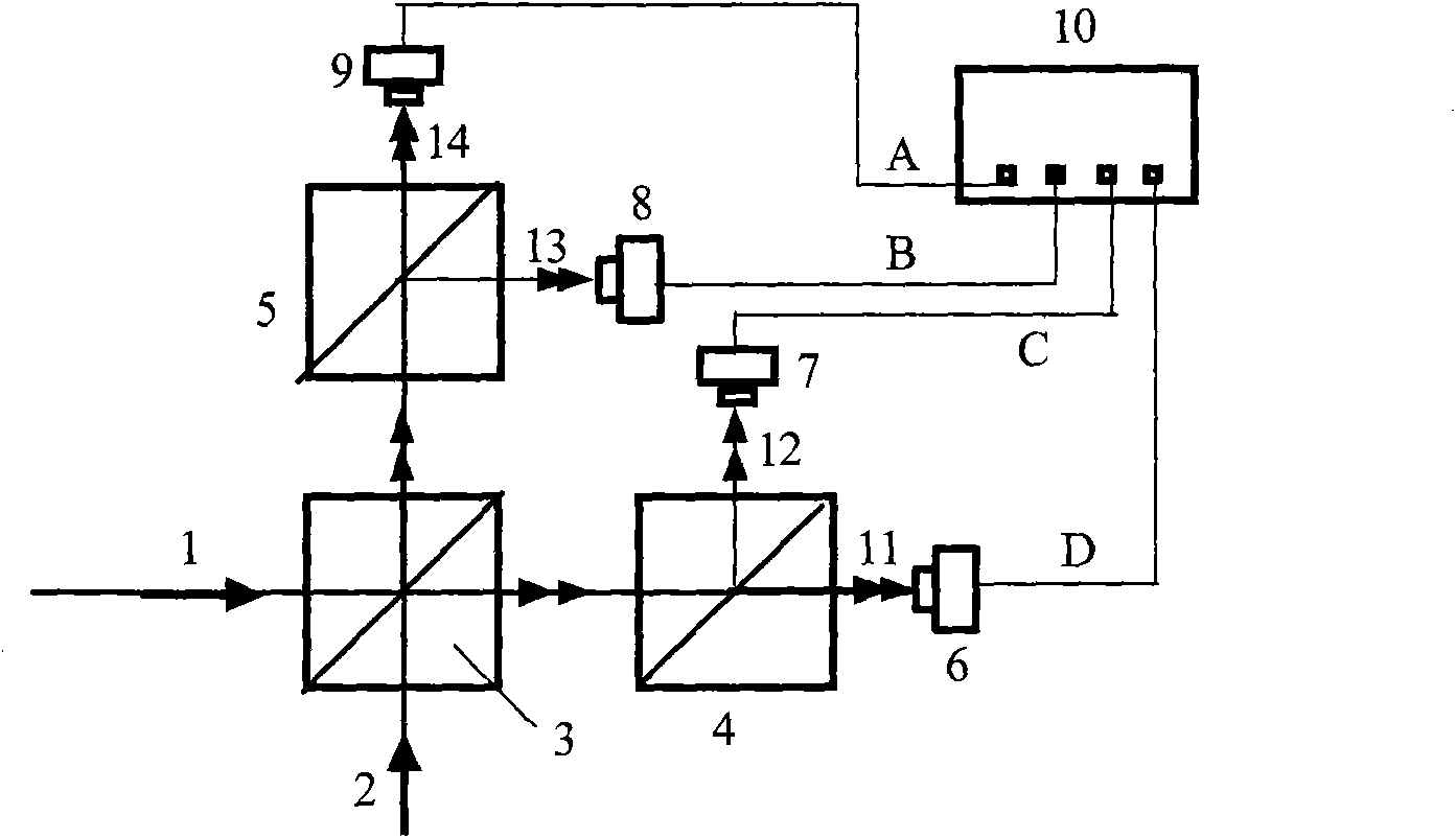
[0016] see first figure 1 , figure 1 It is a schematic structural diagram of the non-polarizing beam splitter phase measuring device of Embodiment 1 of the beam splitter phase measuring device of the present invention. Depend on figure 1 It can be seen that the structure of the non-polarizing beam splitter phase measurement device of the present invention includes the non-polarizing beam splitter to be measured 3, the first polarizing beam splitter prism 4, the second polarizing beam splitting prism 5, the first photodetector 6, the second photodetector device 7, third photodetector 8, fourth photodetector 9 and oscilloscope 10. Its positional relationship is: two mutually perpendicular first light beams 1 and second light beams 2 are incident on the unpolarized beam spl...


PUM


Abstract

The invention relates to a phase measurement device of a beam splitter, which comprises a phase measurement device of an unpolarized beam splitter and a phase measurement device of a polarized beam splitter, wherein the phase measurement device of the unpolarized beam splitter comprises an unpolarized beam splitter to be measured, two polarized beam-splitting prisms, four photoelectric detectors and an oscilloscope; and the phase measurement device of the polarized beam splitter comprises a polarized beam splitter to be measured, two one-half wave plates, two polarized beam-splitting prisms, four photoelectric detectors and an oscilloscope. The phase measurement device can measure the phase relationship of two orthogonal components containing a vertical component (s component) and a parallel component (p component) of transmission light and reflected light of light waves after passing through the beam splitter. The invention is simple in measurement and easy to operate.

Description

technical field [0001] The invention relates to the phase measurement of light waves, specifically measuring the phase relationship between two orthogonal components of the transmitted light and reflected light after the light wave passes through a beam splitting device, including a vertical component (s component) and a parallel component (p component). Background technique [0002] In many optical systems, it is often necessary to use a beam splitter to split a beam of light into two beams of light. The commonly used beam splitters include beam splitters, beam splitters, and beam splitter prisms, which are widely used optical components. For this kind of beam splitting device, almost all devices only measure the splitting ratio, that is, the light intensity energy ratio of the two split beams, and do not measure the phase change relationship of the beam after passing through the splitting device, but in some applications , such as spatial coherent detection, laser radar, e...

Claims


Application Information

Patent Timeline
IPC IPC(8): G01J9/00
Inventor 万玲玉周煜职亚楠孙建锋刘立人
Owner SHANGHAI INST OF OPTICS & FINE MECHANICS CHINESE ACAD OF SCI
Why Eureka
Try Eureka