Lamination method of laminated battery cell of lithium-ion power battery

A power battery and lithium-ion technology, applied in the direction of secondary batteries, battery pack components, circuits, etc., can solve the problems of poor shock resistance and extrusion resistance, shortened cycle life, shortened cycle life, etc., to achieve shock resistance and durability Strong extrusion ability, good shock resistance and extrusion resistance, and the effect of prolonging the cycle life

Active Publication Date: 2011-07-06
常州市金百特锂能源科技有限公司
View PDF0 Cites 0 Cited by
  • Summary
  • Abstract
  • Description
  • Claims
  • Application Information

AI Technical Summary

Problems solved by technology

[0002] At present, there are two main stacking methods for lithium-ion power battery laminated cells: one is the bag-making method, which is to pack the positive electrode or negative electrode between two insulating diaphragms, and then use hot pressing or ultrasonic method to make The positive electrode sheet or the negative electrode sheet is bonded together with the two insulation diaphragms on both sides to form a bag, and then the bag is stacked together, and then wrapped with tape, etc., and the negative electrode on the negative electrode sheet is exposed when wrapping. The positive tab on the ear and the positive electrode sheet has the following defects in the lamination method of this laminated cell: complex process, slow speed, low efficiency, and the insulating diaphragm has the ability to isolate electronics and insulation and has the ability to absorb and hold liquid. However, since the air gap on the edge of the insulating diaphragm is sealed after heat sealing, the ability of the insulating diaphragm to absorb electrolyte and store electrolyte becomes worse, and this deterioration of the ability means the loss of electrolyte, and the loss of electrolyte will cause It causes heat generation and loss of capacity of the lithium-ion power battery, which leads to early attenuation of the lithium-ion power battery and reduced cycle life; another lamination method of lithium-ion power battery laminated cells is the reciprocating folding method, which is machined The method stacks the positive electrode sheet and the negative electrode sheet in the middle of the reciprocally folded insulating diaphragm. This method makes the folded insulating diaphragm easy to be pierced by the edge burrs of the positive electrode sheet and the negative electrode sheet and cause a micro-short circuit, resulting in leakage or leakage of the lithium-ion power battery. self-discharge
And above-mentioned two kinds of methods all have following severe defects: (1), easy to expand, safety risk is big
After the liquid injection and formation of the lithium-ion power battery are completed, the expansion of the laminated cell material after absorbing the electrolyte and the gas generated by charging and formation will cause the lithium-ion power battery to swell. The pressure is uniform, and there will be serious bulges in the middle. Although the round shell does not produce serious bulges like the square shell, there is also the risk and possibility of bulges, and the bulges will increase the internal resistance of the bulge in the middle of the battery. Heat generation will further cause the electrolyte to evaporate, causing the capacity loss of the bulging part, and even lead to early attenuation of the capacity, thereby greatly shortening its cycle life, and even causing damage to the battery. In severe cases, there is a possibility of explosion, which brings unsafe hidden dangers ; (2), poor shock resistance and extrusion resistance
Regardless of whether it is a round or a square laminated battery pack and placed in the casing, because there is no fixation and support, the protection is poor, the laminated battery cell is easy to move in the casing, the shock resistance and extrusion resistance are poor, and it is easy to cause lithium ion damage. Damage to the power battery, which shortens its cycle life

Method used


Image

  • Lamination method of laminated battery cell of lithium-ion power battery
  • Lamination method of laminated battery cell of lithium-ion power battery
  • Lamination method of laminated battery cell of lithium-ion power battery

Examples


Embodiment Construction

[0021] The present invention will be described in further detail below in conjunction with the accompanying drawings and embodiments.

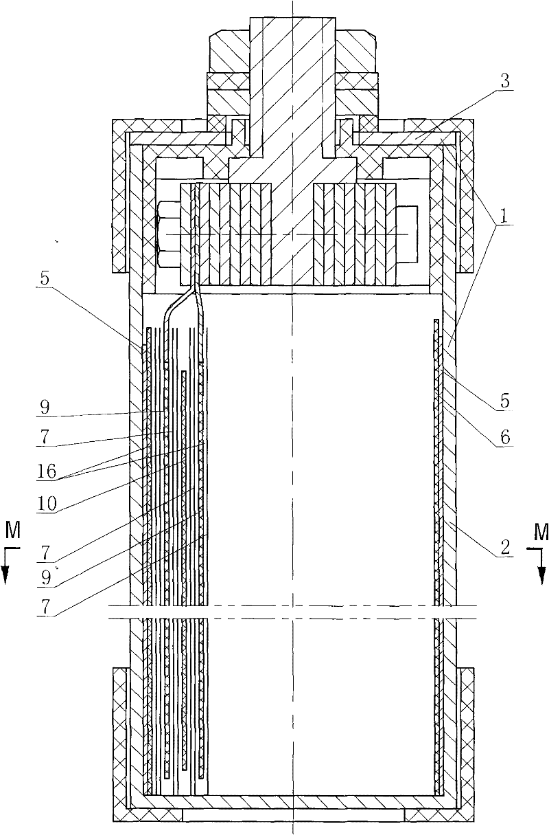
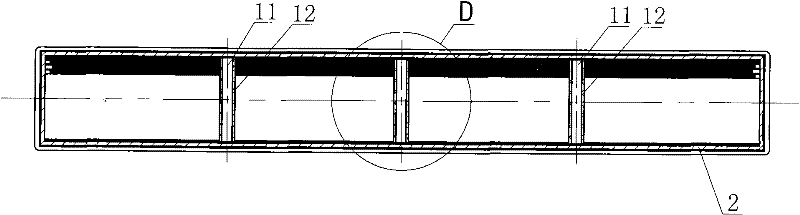
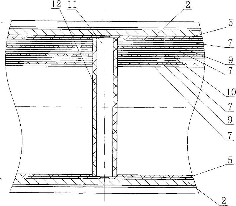
[0022] Such as Figure 1 to Figure 10 As shown, a stacking method of laminated cells of a lithium-ion power battery, the negative electrode sheet 9 and the positive electrode sheet 10 of the laminated cell 16 are arranged alternately in sequence, and the negative electrode sheet 9 and the positive electrode sheet 10 are separated by an insulating diaphragm 7 Open, the outside of the outermost pole piece is also provided with an insulating diaphragm 7, and both ends of the left and right use the negative pole piece 9 as the outermost pole piece, that is, according to the insulating diaphragm 7, the negative pole piece 9, the insulating membrane 7, the positive pole piece 10, Insulating diaphragm 7, negative electrode sheet 9, insulating diaphragm 7, positive electrode sheet 10, insulating diaphragm 7...Insulating diaphragm 7, negative electrode...


PUM


Abstract

A lamination method of a laminated battery cell of a lithium-ion power battery is characterized in that positioning holes are arranged on two side plywood; connecting holes matching the positions of the positioning holes are arranged on negative pole pieces, positive pole pieces and insulating diaphragms of the laminated battery cell; positioning columns pass through the connecting holes and cover the negative pole pieces, the positive pole pieces and the insulating diaphragms outside the positioning columns; the negative pole pieces, the positive pole pieces and the insulating diaphragms arearranged in the specified sequence; the positioning columns are also fixedly connected with the side plywood in the positions of the positioning holes, thereby completing lamination of the laminated battery cell of the lithium-ion power battery. The positioning holes on the two side plywood in the invention can be used as the positioning holes during lamination and the combination points for fixed connection with a shell after lamination completion to enable the laminated battery cell and the shell to be integrated. The lamination method has the advantages of simple process, high lamination efficiency, quick lamination speed, good lamination quality and low machining cost which contributes to low cost of the whole laminated battery cell. The lamination method prolongs the cycle service life of the lithium-ion power battery using the method of the invention and solves the problem of bulge. The positioning holes function as safety valves, thus ensuring high safety.

Description

technical field [0001] The present invention relates to a stacking method of lithium-ion power battery laminated cells. The lithium-ion power battery involved in the invention is mainly used in various hybrid vehicles and pure electric vehicles with lithium-ion power batteries as power sources. It belongs to the field of power batteries. Background technique [0002] At present, there are two main stacking methods for lithium-ion power battery laminated cells: one is the bag-making method, which is to pack the positive electrode or negative electrode between two insulating diaphragms, and then use hot pressing or ultrasonic method to make The positive electrode sheet or the negative electrode sheet is bonded together with the two insulation diaphragms on both sides to form a bag, and then the bag is stacked together, and then wrapped with tape, etc., and the negative electrode on the negative electrode sheet is exposed when wrapping. The positive tab on the ear and the posi...

Claims


Application Information

Patent Timeline
Patent Type & Authority Patents(China)
IPC IPC(8): H01M10/38H01M2/10
CPCY02E60/12Y02E60/10Y02P70/50
Inventor 周金平
Owner 常州市金百特锂能源科技有限公司
Why Eureka
Try Eureka