
Plasma energy converter and an electromagnetic reactor used for producing said converter

A technology of energy converter and plasma, applied in the field of ion physics, can solve the problems of plasma stability and short fusion reaction time

Inactive Publication Date: 2010-01-27
鲍里斯·费奥多罗维奇·波尔托拉茨基
View PDF3 Cites 2 Cited by
  • Summary
  • Abstract
  • Description
  • Claims
  • Application Information

AI Technical Summary

Problems solved by technology

[0004] The limited stability of the plasma and the too short fusion reaction time are disadvantages of known devices
This disadvantage has aerodynamic origin and is associated with many forms of fluctuations in the magnetized plasma

Method used


Image

  • Plasma energy converter and an electromagnetic reactor used for producing said converter
  • Plasma energy converter and an electromagnetic reactor used for producing said converter
  • Plasma energy converter and an electromagnetic reactor used for producing said converter

Examples


Embodiment Construction

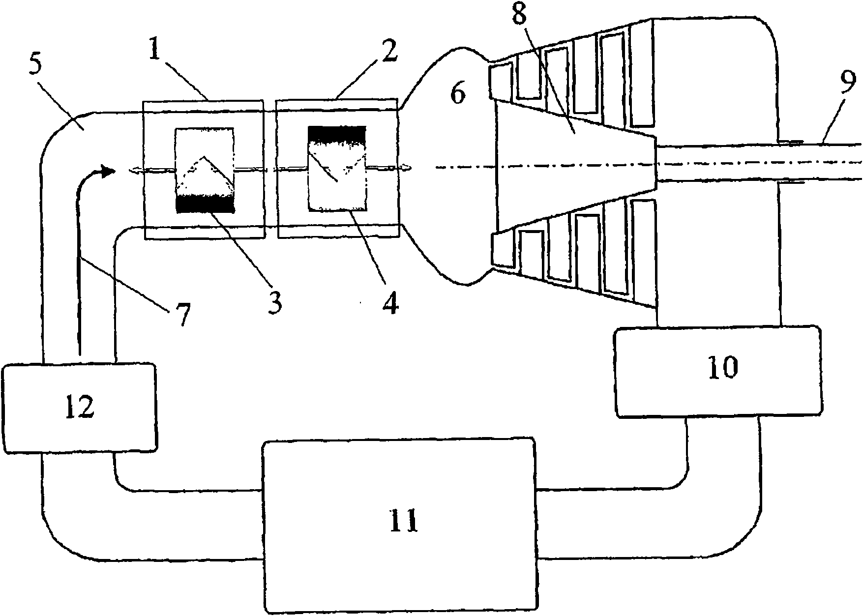
[0021] Such as figure 1 The plasma energy converter of the shown structural diagram comprises the first electromagnetic vortex reactor (1) and The second electromagnetic vortex reactor (2). The working medium (7) fills the input channel (5). The output channel (6) is connected with a mechanical energy converter (8) having an output shaft (9). The output of the mechanical energy converter (8) is connected to the input channel (5) through the cooling box (10), receiver (11) and compressor (12).

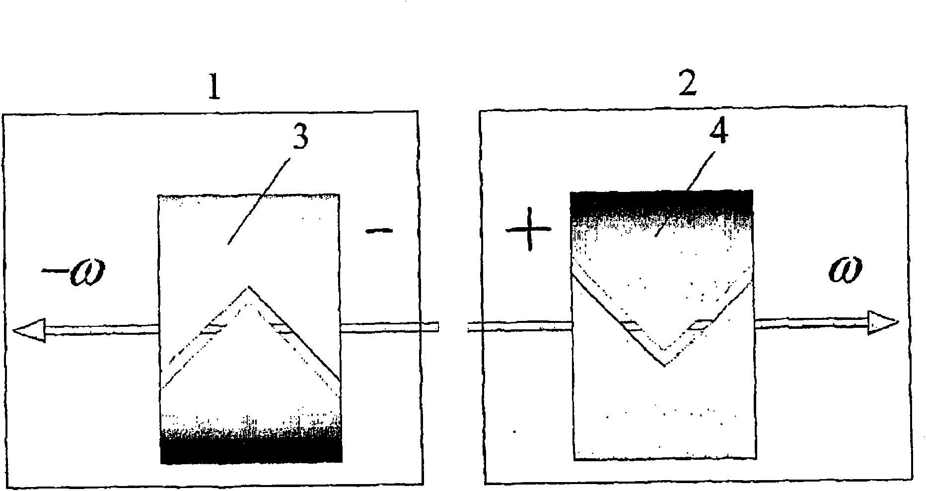
[0022] figure 2 The relative positions of two electromagnetic vortex reactors (3) and (4) are shown, characterized by the opposite charges of their vortex regions (3) and (4), and the opposing directions of rotation, such as their spin.

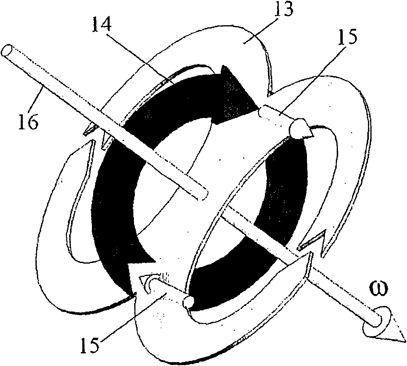
[0023] image 3 The schematically shown field structure corresponds to one state of a rotating alternating electromagnetic vortex field. where the electric field (13) has the shape of a dipole transverse to the vertical axis. The magnetic fiel...


PUM


Abstract

The invention relates to a plasma energy converter and an electromagnetic reactor for producing the converter. The invention relates to a mehtod and a device of plasma physics, especially a system for electromagnetic constraint high-energy plasma, and conditions for executing high-temperature reaction including controlled nuclear fusion reaction. The invention include a working chamber, which includes a working medium placed in the field for electromagnetic system for constraining and heating plasma. The system is at least composed of two electromagnetic vortex reactors which rotate mutually and oppositely with opposite electric charges, and the vortex field is located in the working chamber. The reactor includes a working chamber and a system for exciting the plasma state of the working medium. The system for exciting the plasma state of the working medium includes a concentrator for microwave vortex electromagnetic field, whose axis coincides with the reactor vortex field.

Description

field of invention [0001] The present invention relates to a method and a device mainly related to the field of plasma physics and, in particular, a system for plasma confinement providing conditions for running high temperature reactions including nuclear fusion reactions. The invention can also be used for the plasma separation of crude oil and the activation of other high-temperature reactions. Background technique [0002] The confinement of high-temperature plasma is a key issue in controllable thermonuclear fusion. There are currently two constraint methods. The first method is inertial, eg, relying on a laser to initiate the reaction (see, eg, US Patent No. 6,418,177; Stauffer et al.; July 9, 2002; Int.Cl.H05H 1 / 22, US Cl.376 / 152) . The second method is based on the confinement of high temperature plasmas induced by magnetic fields (Cf. US Patent No. 6,664,740; Rostoker et al. Al of December 16, 2003, IPC G2 1 D 7 / 00, USCl.315 / 111.41). Gathering a large amount of ...

Claims


Application Information

Patent Timeline
IPC IPC(8): H05H1/02G21B1/00
CPCY02E30/126G21D7/00H05H1/16G21B1/05Y02E30/00Y02E30/10
Inventor 鲍里斯·费奥多罗维奇·波尔托拉茨基
Owner 鲍里斯·费奥多罗维奇·波尔托拉茨基
Learn More