Pipeline cleaning method

A pipeline flushing and pipeline technology, applied in cleaning methods and utensils, chemical instruments and methods, cleaning hollow objects, etc., can solve the problems of low cleanliness and long time consumption

Active Publication Date: 2011-05-04
CHINA HUAYE GROUP
View PDF5 Cites 0 Cited by
  • Summary
  • Abstract
  • Description
  • Claims
  • Application Information

AI Technical Summary

Problems solved by technology

[0008] In order to solve the problems of long time consumption and low cleanliness of traditional cleaning methods, the present invention proposes a pipeline flushing method capable of fast cleaning and high cleanliness

Method used


Image

  • Pipeline cleaning method
  • Pipeline cleaning method

Examples


Embodiment Construction

[0018] In order to illustrate the above-mentioned pipeline cleaning method more clearly, it will be described in further detail below in conjunction with the accompanying drawings:

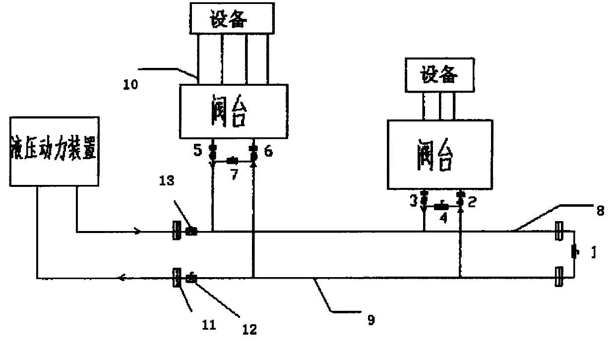
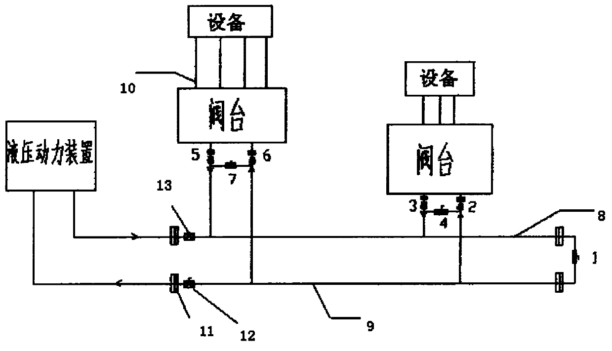
[0019] figure 1 It is a schematic diagram showing the structure of the cleaning device used in the pipeline cleaning method according to the present invention. like figure 1 As shown, the hydraulic device in the embodiment is mainly composed of hydraulic power device, valve table, equipment and other devices, and each device is connected by oil return pipeline 8, oil supply pipeline 9, plus various branch pipelines, short pipelines, etc. The pipes can be connected by socket welding or high-diameter flange bolts, without using threaded fittings to ensure the cleanliness between pipes, such as figure 1 As shown, bypass valves such as 1, 2, 3, 4, 5, 6, and 7 are installed between each pipeline. When the valve is closed, it acts as an isolation valve, which can block the entry of cleaning oil and ot...


PUM


Abstract

The invention relates to a pipeline cleaning method, which uses cleaning oil as medium and uses a pump to clean forcibly and circularly. The pipeline cleaning method comprises the following steps: 1) steps of processing and installing the pipeline: respectively installing a separating valve at a main pipeline, a branch pipeline and connecting part of bypass pipelines; 2) steps of installing a temporary cleaning device and disassembling the branch pipeline; 3) step of primary cleaning; 4) step of restoring the normal pipelines; and 5) step of secondary cleaning. Compared with the traditional construction process, the construction technique increases a control valve on the original basis, increases the step of reverse cleaning, uses the control of the bypass valve, has circular and thoroughcleaning, high cleanness, short time and low cost, avoids the defects that the dead angles are formed in cleaning and the like and has better technical effect and promotion value.

Description

technical field [0001] The invention relates to a pipeline flushing method, in particular to a pipeline flushing method in hydraulic, lubricating and other equipment, and belongs to the field of pipeline installation and construction. Background technique [0002] Hydraulic, lubricating and other equipment has the characteristics of reliable performance and convenient use, and is used more and more widely in today's industrial equipment and production. [0003] However, since new equipment will come into contact with some metal working fluids, anti-rust oils and greases during processing and assembly, these oils contain more polar substances, and some equipment must be tested before leaving the factory. Some oil impurities will remain in the equipment, and a small amount of metal chips will remain in the equipment during the processing of the equipment. If the new equipment is not cleaned before refueling, all these impurities will enter the lubricating oil, which will seri...

Claims


Application Information

Patent Timeline
Patent Type & Authority Patents(China)
IPC IPC(8): B08B9/032
Inventor 刘增柱闫世新樊晓辉李正刚
Owner CHINA HUAYE GROUP
Why Eureka
Try Eureka