Mounting structure of gas control valve of cutting machine

A technology of gas control valve and installation structure, which is applied in the direction of gas flame welding equipment, manufacturing tools, welding equipment, etc. It can solve the problems of inconvenient operation and adjustment, occupying a lot of space, and unintuitive operation, and achieves beautiful production, simple assembly, and easy installation. The effect of simple structure

Inactive Publication Date: 2010-02-03
WUXI HUALIAN PRECISION MACHINERY
View PDF0 Cites 7 Cited by
  • Summary
  • Abstract
  • Description
  • Claims
  • Application Information

AI Technical Summary

Problems solved by technology

[0002] At present, the cutting machine gas control valve installation structure used in CNC flame cutting equipment is generally three-way gas control. Some are installed on the beam, which is convenient for viewing but inconvenient to operate and adjust. not intuitive
The original control valve structure takes up a lot of space, and there is no high preheating oxygen. The preheating time is long and the efficiency is low.

Method used


Image

  • Mounting structure of gas control valve of cutting machine
  • Mounting structure of gas control valve of cutting machine
  • Mounting structure of gas control valve of cutting machine

Examples


Embodiment Construction

[0011] Below the present invention will be further described in conjunction with the embodiment of accompanying drawing:

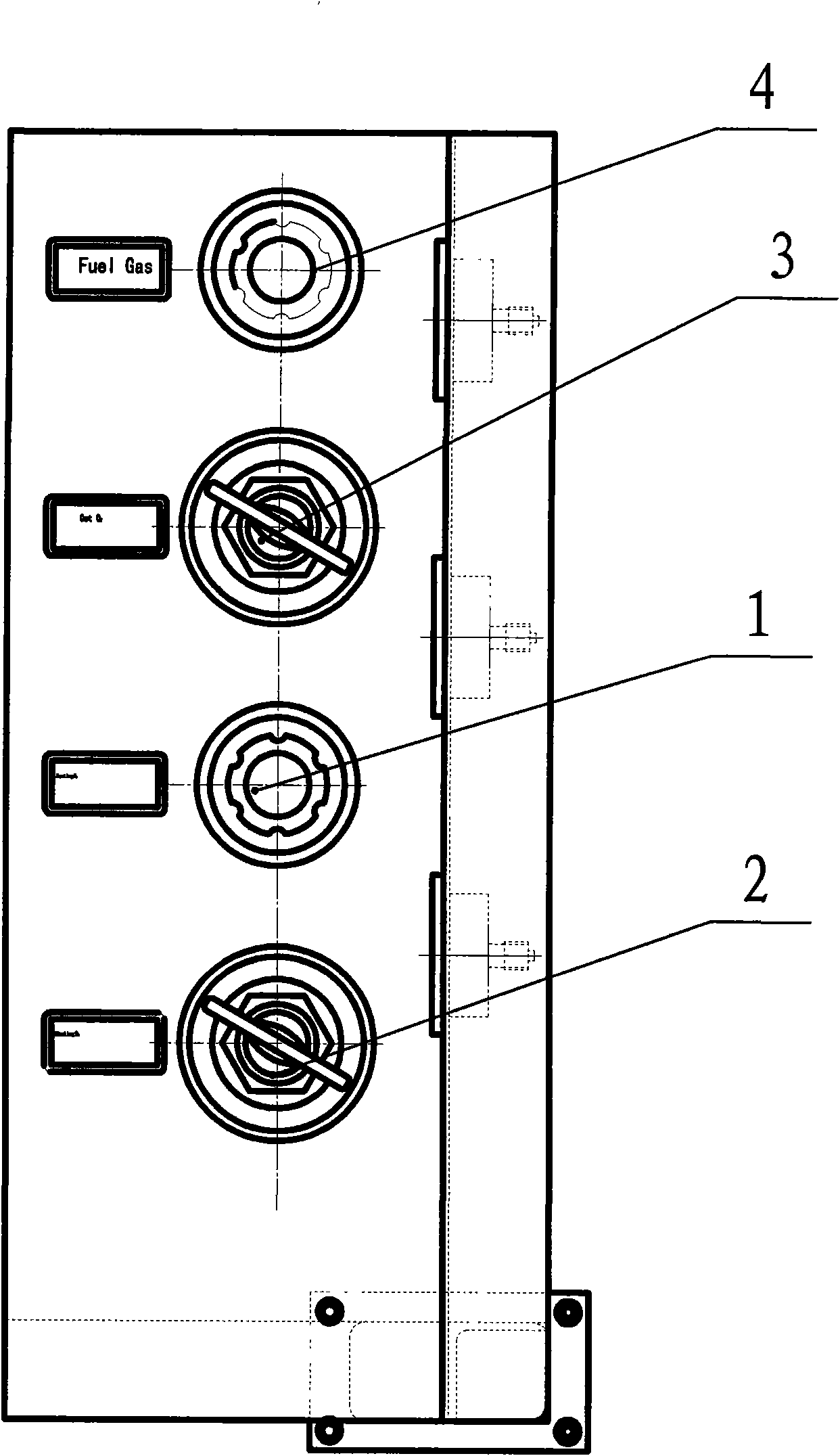
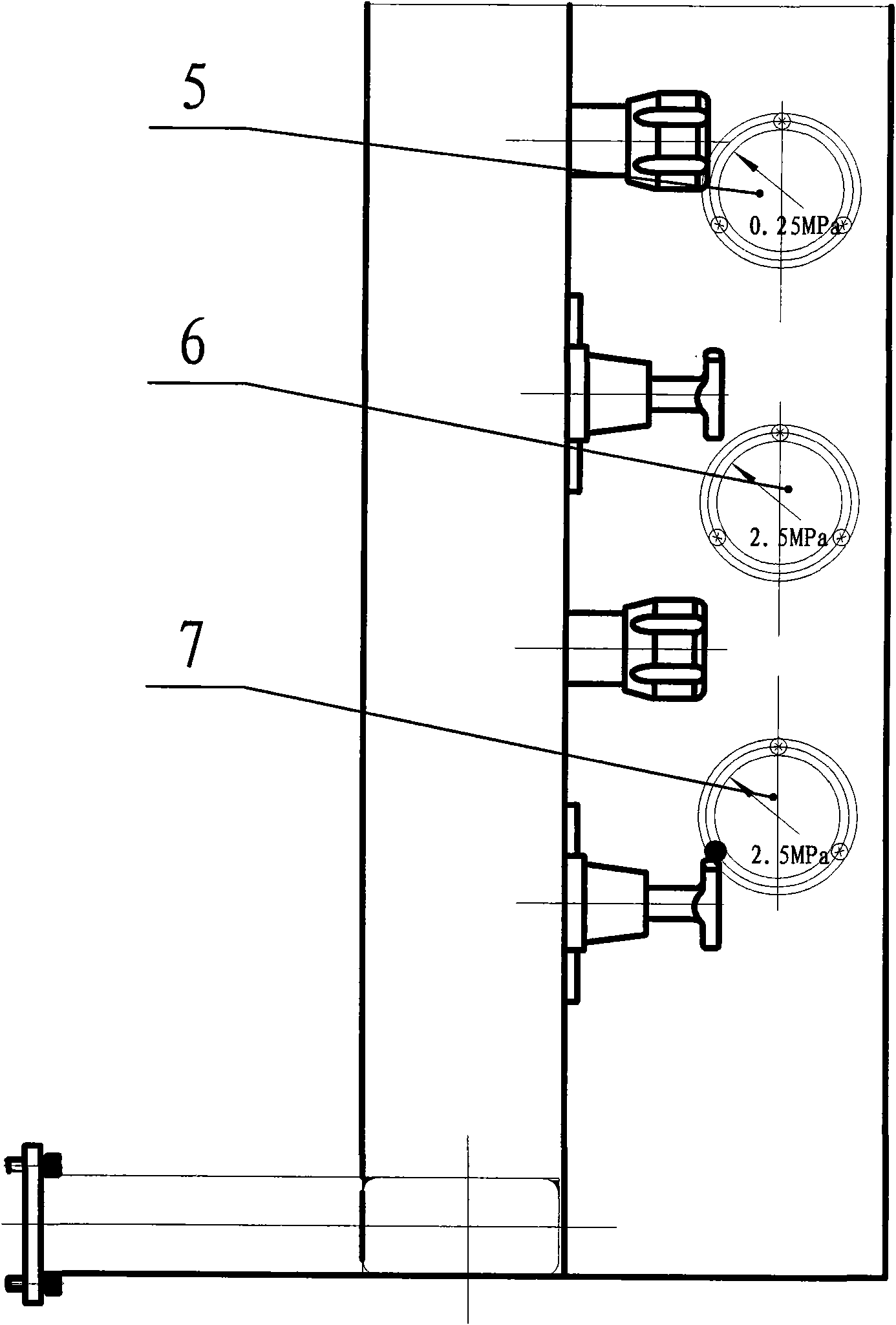
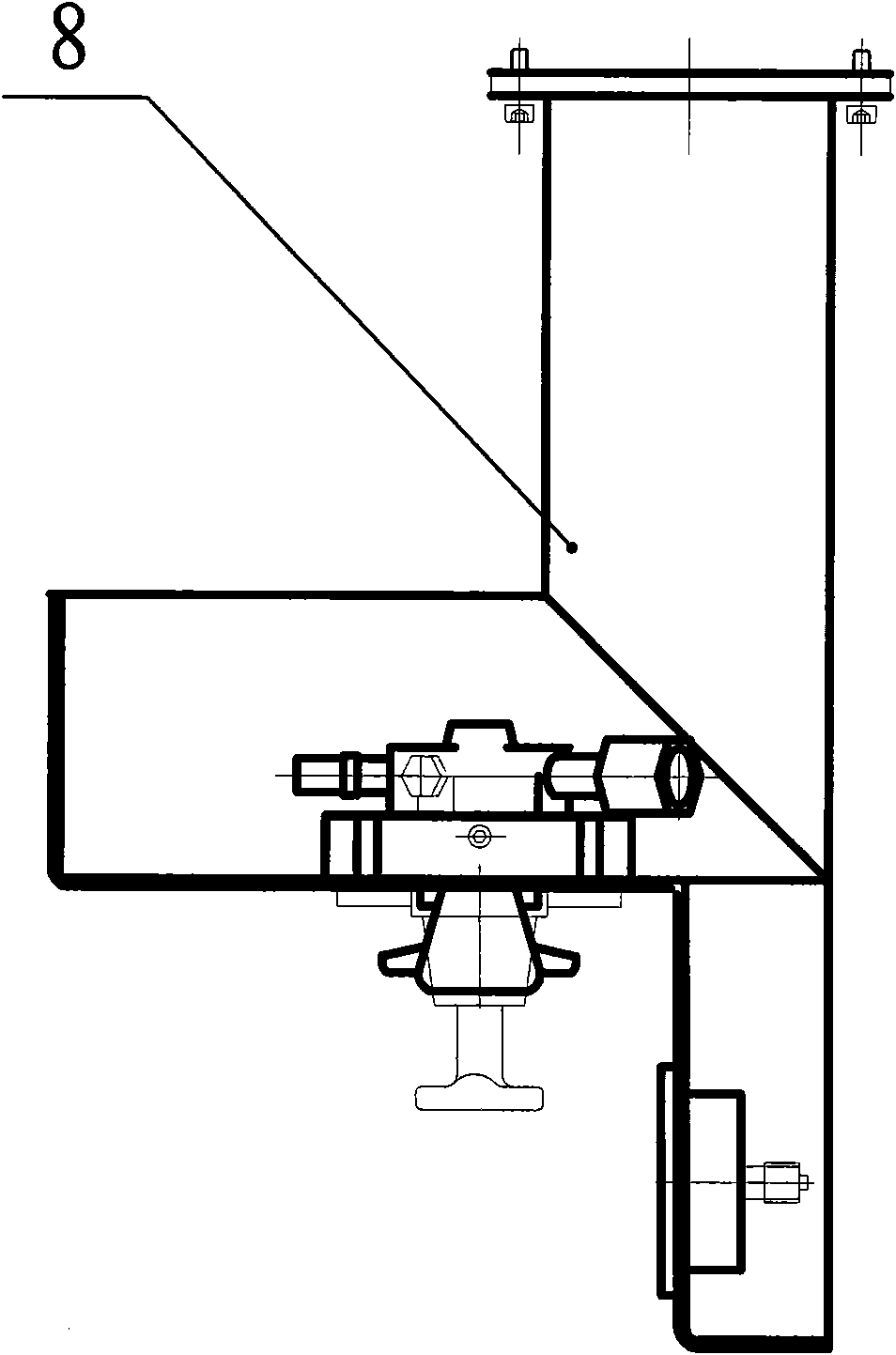
[0012] Such as Figure 1 ~ Figure 3 As shown, including low preheating oxygen pressure reducing valve 1, high preheating oxygen pressure reducing valve 2, cutting oxygen pressure reducing valve 3, gas pressure reducing valve 4, preheating oxygen pressure gauge 5, cutting oxygen pressure gauge 6, gas pressure Table 7, the composition of the mounting plate 8 and so on.

[0013] The installation structure of the gas control valve of the CNC cutting machine of the present invention mainly adopts the side of the installation plate 8 to respectively install various pressure reducing valves: low preheating oxygen pressure reducing valve 1, high preheating oxygen pressure reducing valve 2, cutting oxygen pressure reducing valve 3, gas pressure reducing valve Pressure reducing valve 4, various pressure gauges are installed on the front of mounting plate 8: preheat...


PUM


Abstract

The invention relates to a mounting structure of a gas control valve of a cutting machine. The mounting structure is characterized by comprising a low preheating oxygen relief valve, a high preheatingoxygen relief valve, a cutting oxygen relief valve, a fuel gas relief valve, a preheating oxygen pressure gauge, a cutting oxygen pressure gauge, a fuel gas pressure gauge and an mounting plate; andthe mounting plate is respectively provided with the low preheating oxygen relief valve, the high preheating oxygen relief valve, the cutting oxygen relief valve and the fuel gas relief valve on sidesat sides, and a front surface of the mounting plate is respectively provided with the preheating oxygen pressure gauge, the cutting oxygen pressure gauge and the fuel gas pressure gauge. The mountingplate has a rectangular structure and formed by flanging plates. The mounting structure of a gas control valve of a cutting machine has simple and visual structure, convenient adjustment, simple assembly, high and low pressure switching and the rectangular mounting plate with beautiful appearance and space saving.

Description

technical field [0001] The invention relates to a gas control valve installation structure of a cutting machine, in particular to a gas control system used in numerically controlled flame cutting equipment, and belongs to the technical field of cutting equipment. Background technique [0002] At present, the cutting machine gas control valve installation structure used in CNC flame cutting equipment is generally three-way gas control. Some are installed on the beam, which is convenient for viewing but inconvenient to operate and adjust. Not intuitive. The original control valve structure takes up a lot of space, and the preheating time is long and the efficiency is low when there is no high preheating oxygen. Contents of the invention [0003] The purpose of the present invention is to overcome the deficiencies in the prior art, so as to provide a cutting machine gas control valve installation structure with simple structure, direct view, convenient adjustment and easy as...

Claims


Application Information

Patent Timeline
Patent Type & Authority Applications(China)
IPC IPC(8): B23K7/10
Inventor 邵燕瑛吴美琴范彬
Owner WUXI HUALIAN PRECISION MACHINERY
Why Eureka
Try Eureka