
Full-automatic lensmeter

A focal meter, fully automatic technology, applied in the field of focal meter, can solve problems such as troublesome operation, offset of reticle center, displacement of cylinder lens axis, etc.

Inactive Publication Date: 2010-02-03
ZHEJIANG UNIV
View PDF0 Cites 4 Cited by
  • Summary
  • Abstract
  • Description
  • Claims
  • Application Information

AI Technical Summary

Problems solved by technology

[0002] The degree meter is one of the necessary optometry instruments for optical retail stores. It can be divided into ordinary manual adjustment type focal length meter and computer focal length meter, commonly known as one degree meter. The measurement of ordinary manual adjustment type focal length meter is controlled by humans. The vertex value of the measured spectacle lens is determined by observing the visual standard of the instrument with the naked eye. The measured value is greatly affected by human subjectivity, and the measurement accuracy is relatively low.
The measurement of the existing computer focimeter is completed by computer, which can eliminate human subjective factors, but it has the defects of troublesome operation and low measurement accuracy
The main reasons are: (1). The zero adjustment before measurement is cumbersome, and the optical center of the lens is difficult to locate accurately
(2). During the measurement process, it needs to be continuously adjusted by the tester and confirmed with the naked eye to obtain a clear mark image. There are human factors that cause measurement errors
(3). Due to the mechanical structure of the manual lens meter, the center of the reticle often shifts after a certain period of time, causing the axis of the cylinder to shift and causing errors.
(4). Due to the parallax of the measuring personnel and the mechanical clearance of the reading disc, there is a scale error

Method used


Image

  • Full-automatic lensmeter
  • Full-automatic lensmeter
  • Full-automatic lensmeter

Examples


Embodiment Construction

[0061] The present invention will be further described below in conjunction with the accompanying drawings.

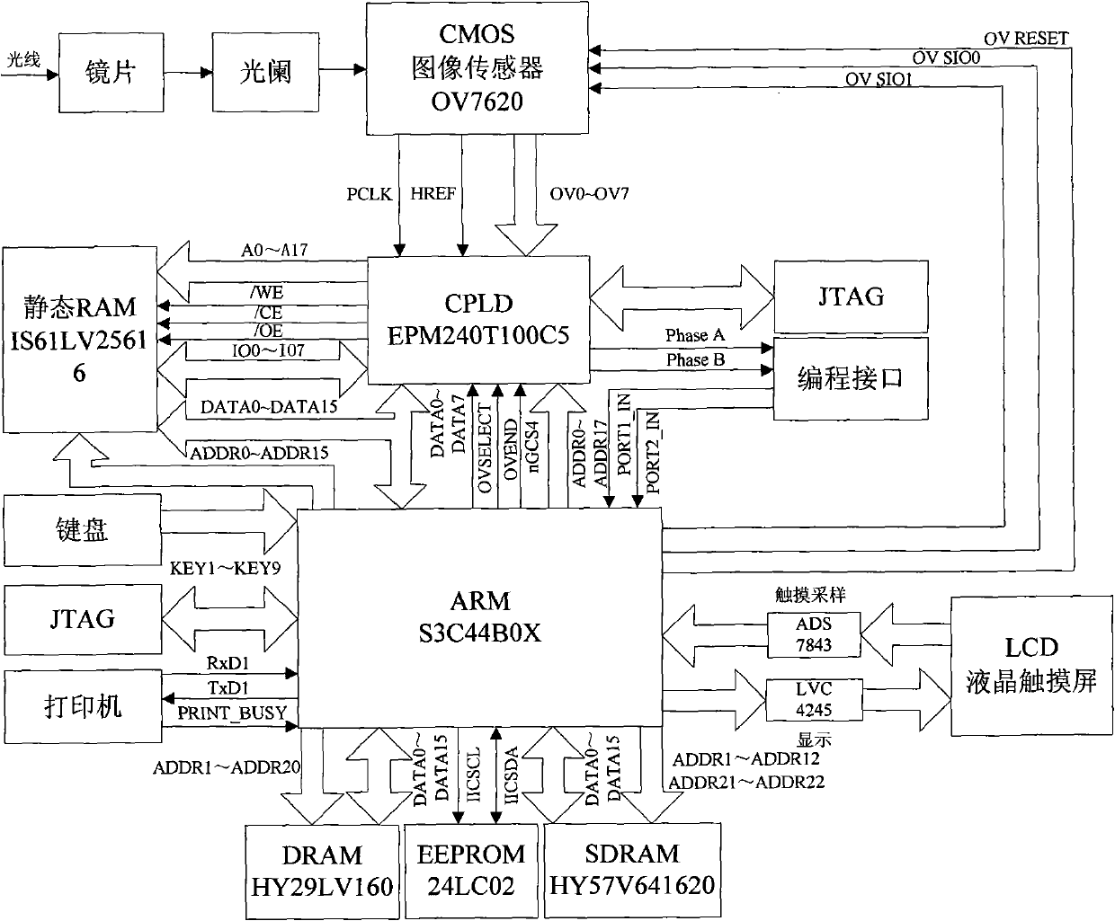
[0062] refer to Figure 1 to Figure 9 , a fully automatic lens meter, comprising: an image sensor, used to collect light signals passing through the lens to be detected;

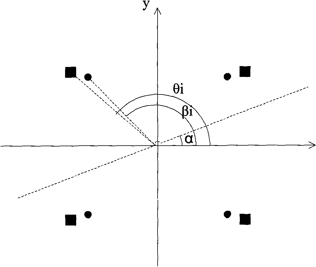
[0063] A programmable logic device and a microprocessor ARM module are used to receive the optical signal, and the coordinates of the initial spot position are set as (x i ,y i ), the distance to the center of the circle is R i , the angle between the line connecting the origin of the coordinates and the x-axis is β i ; The coordinates of the spot position after putting in the lens are (x i ,y i ), the distance to the center of the circle is r i , the angle between the line connecting the origin of the coordinates and the x-axis is θ i . The included angle between the baseline of the astigmatism and the x-axis is α, and the coordinates of converting the above two points into the coordinate sy...


PUM


Abstract

The invention relates to a full-automatic lensmeter which comprises an image sensor, a CPLD module and an ARM module, wherein the image sensor is used for collecting optical signals passing through alens to be detected, and the CPLD module and the ARM module are used for processing and controlling data. Coordinates of an initial light spot position are set to be (xi, yi), a distance to the centerof a circle is R, and an included angle formed by a connection line with the origin of the coordinates and the x axis is beta; after a lens is put, the coordinates of the light spot position is(*i, *i), the distance to the center of the circle is r, and the included angle formed by the connection line with the origin of the coordinates and the x axis is theta. The included angle of abase line of a dispersing lens and the x axis is alpha, and after the coordinates of the two pairs of the coordinates shifted into a coordinate system which uses the base line as the x axis are respectively (xi', yi') and (*i', *i'), wherein the subscripts i of the variables respectively represent four light spots, and all the four light spots or two light spots with the furthest distances are selected to carry out least-squares approximation so as to obtain the concave-sphere degree, the concave-cylinder degree and a base line angle. A distance x1 from the rear vertex of the lens to a diaphragm and a distance x2 from the diaphragm to an area array of the CCD image sensor are substituted into a lens vertex dioptrie expression calculated by the definitions of an index path and vertex dioptrie so as to obtain a vertex dioptrie value. The invention has convenient operation and high measuring precision.

Description

technical field [0001] The invention relates to the field of optometry instruments, in particular to a lens meter. Background technique [0002] The degree meter is one of the necessary optometry instruments for optical retail stores. It can be divided into ordinary manual adjustment type focal length meter and computer focal length meter, commonly known as one degree meter. The measurement of ordinary manual adjustment type focal length meter is controlled by humans. The vertex value of the measured spectacle lens is judged by observing the visual mark of the instrument with the naked eye. The measured value is greatly affected by human subjectivity, and the measurement accuracy is relatively low. The measurement of the existing computer focimeter is completed by computer, which can eliminate human subjective factors. However, it has the disadvantages of cumbersome operation and low measurement accuracy. The main reasons are: (1). The zero adjustment before measurement is ...

Claims


Application Information

Patent Timeline
IPC IPC(8): G01M11/02
Inventor 刘政陈正亮李江
Owner ZHEJIANG UNIV
Learn More