Optical focusing device

A technology of optical focusing and accommodating space, applied in focusing devices, optics, optical components, etc., can solve problems such as jamming, pause, jumping, affecting the accuracy and reliability of focusing, and achieve convenient operation and simple structure. Effect

Inactive Publication Date: 2010-02-03
SONY CORP
View PDF6 Cites 32 Cited by
  • Summary
  • Abstract
  • Description
  • Claims
  • Application Information

AI Technical Summary

Problems solved by technology

However, in the above-mentioned focusing mechanism, the multi-stage focusing effect is realized by the cam surface designed as a multi-stage structure. When the cam surface of the multi-stage structure is toggled, especially in two adjacent stages When switching between surfaces, it is likely to cause jamming, pauses, jumps, etc., which will affect the accuracy and reliability of focusing

Method used


Image

  • Optical focusing device
  • Optical focusing device
  • Optical focusing device

Examples


Embodiment Construction

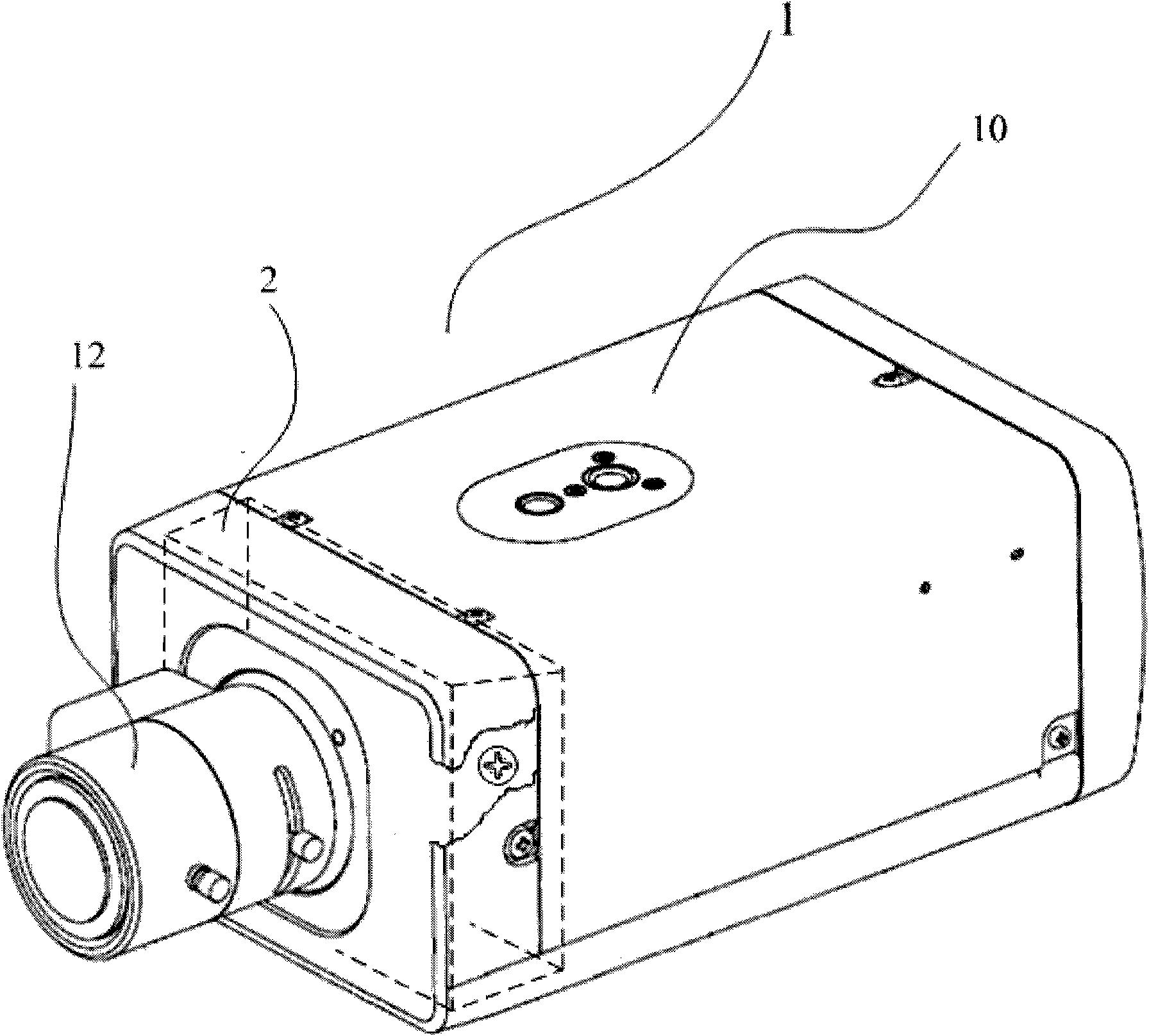
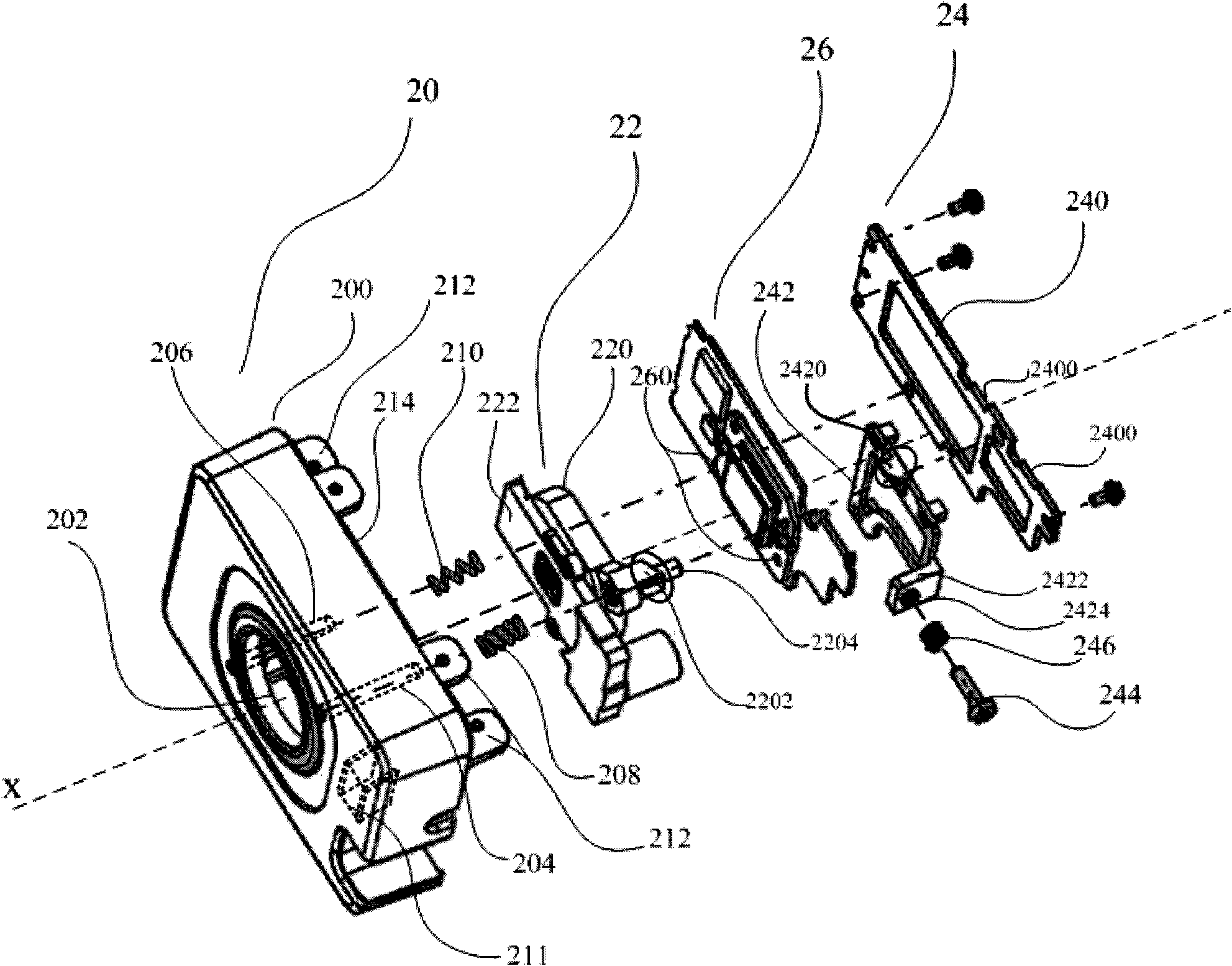
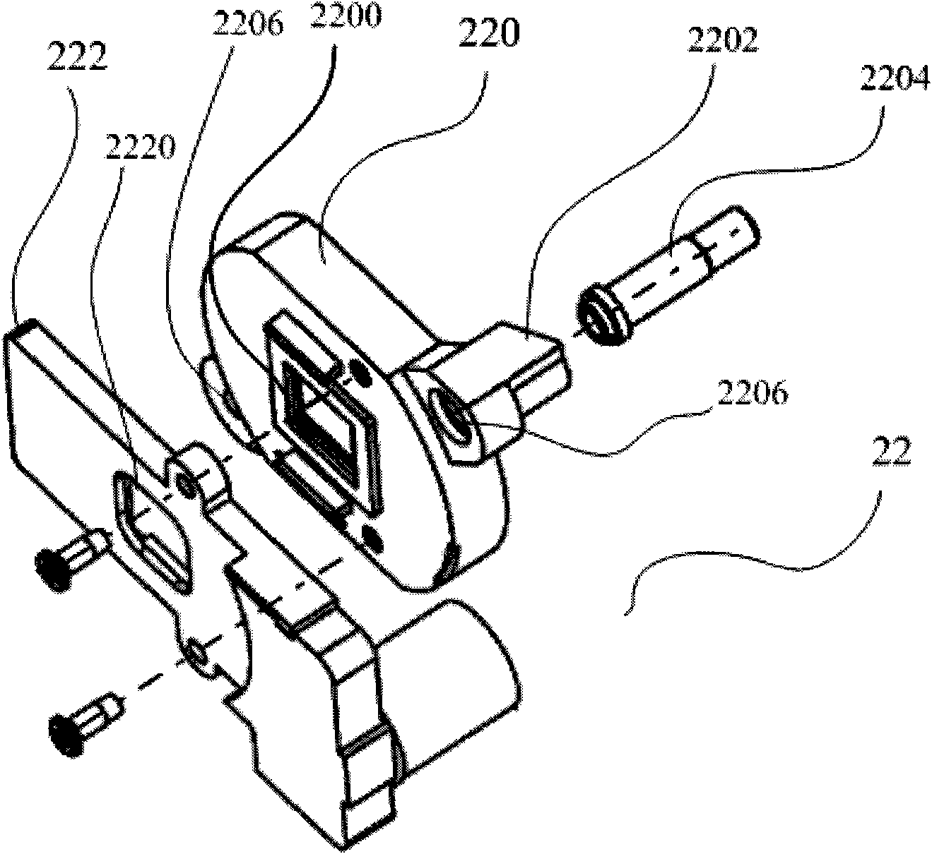
[0025] The present invention provides an optical focusing device, comprising: a casing having an accommodating space, a light hole, and a guide shaft arranged along the axial direction of the light hole; The image sensor panel in the accommodating space of the housing, the image sensor panel has an image sensor, and a first transmission part; The moving slider and the adjustment element are provided with a second transmission part corresponding to the first transmission part on the slider. The invention uses a simple mechanical structure to generate force on the image sensor panel and drive it to move along the axial direction of the optical hole through the sliding part during the movement along the direction perpendicular to the axis of the optical hole to adjust the distance between the image sensor and the lens. distance for optical focusing. Embodiments of the present invention will be described below by taking a surveillance camera as an example in conjunction with the ...


PUM


Abstract

The invention provides an optical focusing device, which comprises a shell, an image sensor component and an actuating component. The actuating component actuates to drive an image sensor panel provided with an image sensor in the image sensor component to move along an axis direction of an aperture so as to adjust the distance between the image sensor panel and a lens, thereby realizing the optical focusing. The optical focusing device of the invention has the advantages of improving the adjustment precision and the stability of focusing, along with simple structure and convenient operation.

Description

technical field [0001] The invention relates to an optical focusing device. Background technique [0002] With the development of digital electronic technology, consumer electronic products with imaging functions, such as surveillance cameras, ordinary digital cameras, digital cameras, and mobile phones with camera functions, have been widely used. [0003] Taking a surveillance camera as an example, when the camera shoots a target object, the lens captures an image, which is refracted on an image sensor (such as CCD, CMOS), and the image sensor converts the optical signal into an electrical signal for output. If the focal length of the camera is fixed, the size of the target object on the screen will also change as the distance to the target object changes. To maintain the clarity of the image, it is necessary to adjust the distance between the lens plane and the focal plane. The imaging size of the target object is controlled at an appropriate size, so that the lens can a...

Claims


Application Information

Patent Timeline
IPC IPC(8): G03B13/32G02B7/04
Inventor 段琼霞芭蕉丰
Owner SONY CORP
Why Eureka
Try Eureka