Method for realizing low-frequency rotary constant high-intensity magnetic field

A realization method and technology of strong magnetic field, applied in the directions of magnetic therapy, using variable magnetic field generated by mechanical movement, electrotherapy, etc., can solve the problems of leakage of magnetic force lines and insufficient magnetic therapy effect, so as to prevent interference and reduce the amount of magnets. , good effect of magnetic therapy

Inactive Publication Date: 2010-02-03
深圳市恒安鸿源磁科技有限公司
View PDF3 Cites 7 Cited by
  • Summary
  • Abstract
  • Description
  • Claims
  • Application Information

AI Technical Summary

Problems solved by technology

[0003] Aiming at the above-mentioned disadvantages that the magnetic therapy equipment in the prior art adopts an open magnetic field, which is prone to leakage of magnetic force lines and insufficient magnetic therapy effect, the present invention provides a new method for realizing a low-frequency rotating constant strong magnetic field, which uses an even number A strong magnet, the strong magnet is fixedly installed on the magnetic conduction arm, the cross section of the strong magnet is in a geometric shape without edges and corners, which greatly reduces the leakage of the magnetic force lines around the strong magnet and the amount of magnets

Method used


Image

  • Method for realizing low-frequency rotary constant high-intensity magnetic field
  • Method for realizing low-frequency rotary constant high-intensity magnetic field
  • Method for realizing low-frequency rotary constant high-intensity magnetic field

Examples


Embodiment 1

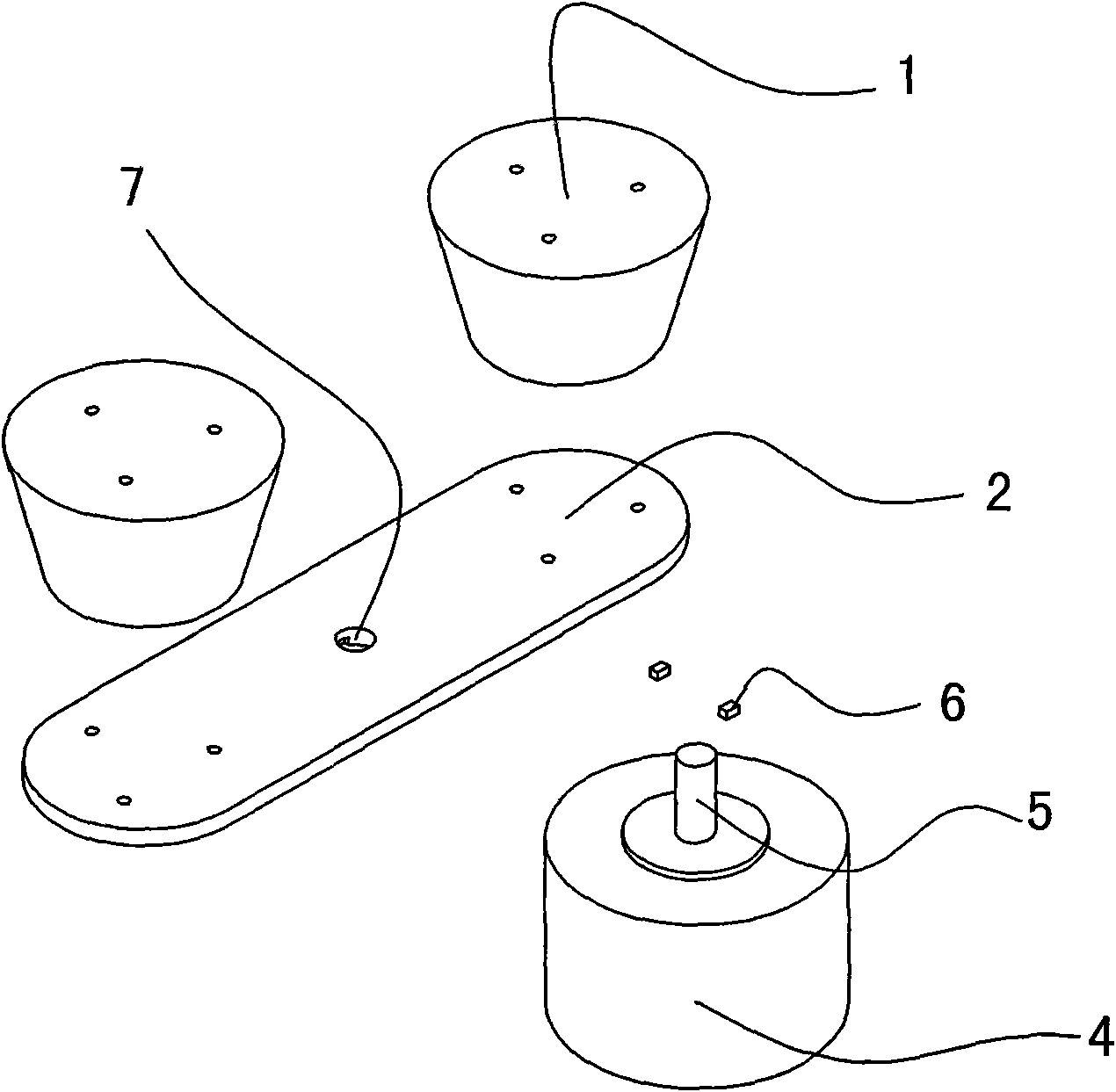
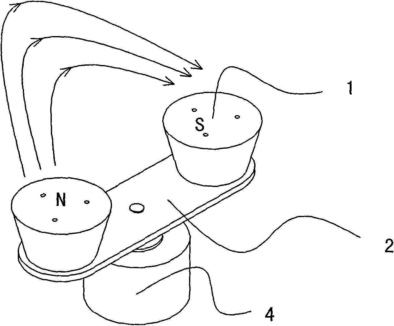
[0024] Embodiment 1: Please refer to the attached figure 1 And attached figure 2 , the present invention mainly includes a strong magnet 1, a magnetically conductive spiral arm 2 and a rotating motor 4. In the present embodiment, the magnetically conductive spiral arm 2 is made of A3 steel plate. During specific implementation, it can also be made of other magnetically conductive materials. The swing arm 2 is in the shape of a long strip, and a strong magnet 1 is fixedly installed at both ends respectively. In this embodiment, the strong magnet 1 is in the shape of a truncated cone. In the present embodiment, the smaller side (i.e. the lower surface) of the strong magnet 1 is fixedly mounted on the magnetically conductive spiral arm 2, and is defined as the connection surface of the magnet 1, and the larger side (i.e. the upper surface) is the action surface of the strong magnetic field. Defined as the free surface of magnet 1. In this embodiment, the strong magnet 1 is fix...

Embodiment 2

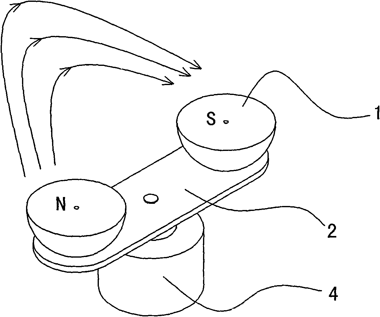
[0025] Embodiment two: Please refer to the attached image 3 , the present embodiment also includes a strong magnet 1, a magnetically conductive spiral arm 2 and a motor 4. In this embodiment, the strong magnet 1 is hemispherical, and the lower surface of the strong magnet 1 (that is, the point on the spherical cap corresponding to the center of the bottom surface) is fixed. Installed on the magnetically conductive spiral arm 2, the upper surface (that is, the bottom plane) is a strong magnetic field action surface. In this embodiment, the strong magnet 1 is fixed and installed on the magnetically conductive spiral arm 2 by screws, and other connection methods may also be used during specific implementation. In this embodiment, the motor 4 is also used to drive the magnetically conductive spiral arm 2 and the strong magnet 1 on the magnetically conductive spiral arm 2 to perform low-frequency rotational motion.

Embodiment 3

[0026] Embodiment three: Please refer to the attached Figure 4 , including strong magnet 1, magnetic conduction arm 2 and motor 4 equally in the present embodiment, in the present embodiment, strong magnet 1 is conical frustum shape, and the cross section of strong magnet 1 is oval, and strong magnet 1 lower surface (being relatively The small side) is fixedly installed on the magnetically conductive spiral arm 2, and the upper surface (that is, the larger side) is a strong magnetic field action surface. In this embodiment, the strong magnet 1 is fixed and installed on the magnetically conductive spiral arm 2 by screws, and other connection methods may also be used during specific implementation. In this embodiment, the rotating motor 4 is also used to drive the magnetically conductive spiral arm 2 and the strong magnet 1 on the magnetically conductive spiral arm 2 to perform low-frequency rotational motion.


PUM


Abstract

The invention discloses a method for realizing a low-frequency rotary constant high-intensity magnetic field. More than two high-intensity magnetic bodies with an even number and a magnetic spiral armare arranged; each high-intensity magnetic body is symmetrically and fixedly mounted on the same side of the magnetic spiral arm; the magnetic poles of a free surface of the two symmetrical high-intensity magnetic bodies are opposite to each other; the area of the free surface of the high-intensity magnetic body is greater than the area of a connecting surface; the cross section of the high-intensity magnetic body is an edge-free geometric shape; and a rotating device drives the magnetic spiral arm and the high-intensity magnetic body to rotate. The invention can prevent flux leakage of the magnetic body around so that a magnetic line is centralized to emit upwards without flux leakage in other directions, thereby ensuring the intensity of the magnetic field in a usable direction, effectively preventing interference on other electric appliances and ensuring the highest upward emitting height of the magnetic line, the strongest magnetic line and the best magnetic therapy effect.

Description

technical field [0001] The invention discloses a method for realizing magnetic therapy, in particular a method for realizing low-frequency rotating constant strong magnetic field. Background technique [0002] Magnetic fields have obvious effects on the human body and other organisms, water or chemical agents. In view of this, magnetic fields are applied to the human body to treat the human body with local strong magnetic fields, commonly known as magnetic therapy. Magnetic therapy is no stranger to modern medicine, and magnetic therapy instruments are not uncommon, such as: Chinese patent (application number: 88214746.4) "electric magnetic therapy machine", Chinese patent (application number: 86206534) "rotating magnetic machine", the United States Patent (Application No. 4,537,141) "Magnetic Device for Non-surgical Elimination of Calcium Deposition in Human Body", etc. But there are different deficiencies in all. For the deficiencies of the above-mentioned patents, the ap...

Claims


Application Information

Patent Timeline
Patent Type & Authority Applications(China)
IPC IPC(8): H01F7/02A61N2/12A61N2/08
Inventor 张功弼
Owner 深圳市恒安鸿源磁科技有限公司
Why Eureka
Try Eureka