Unlock instant, AI-driven research and patent intelligence for your innovation.

Intake manifold for multi-cylinder internal combustion engine

A technology of intake manifold and internal combustion engine, which is applied in the direction of fuel air intake port, internal combustion piston engine, combustion air/combustion-air treatment, etc. It can solve the problem of volume efficiency reduction, hindering the smooth flow of intake air in the intake collection chamber, etc. problems, achieve the effects of suppressing pressure fluctuations, preventing complications, and improving volumetric efficiency

Active Publication Date: 2010-02-03
HONDA MOTOR CO LTD +1
View PDF1 Cites 5 Cited by
  • Summary
  • Abstract
  • Description
  • Claims
  • Application Information

AI Technical Summary

Problems solved by technology

[0005] However, the shape of the manifold formed based on the rigidity of the manifold as described above or the requirement for its shape prevents the smooth flow of intake air in the intake manifold and leads to a decrease in volumetric efficiency.

Method used


Image

  • Intake manifold for multi-cylinder internal combustion engine
  • Intake manifold for multi-cylinder internal combustion engine
  • Intake manifold for multi-cylinder internal combustion engine

Examples


Embodiment Construction

[0018] Hereinafter, embodiments of the present invention will be described with reference to the drawings.

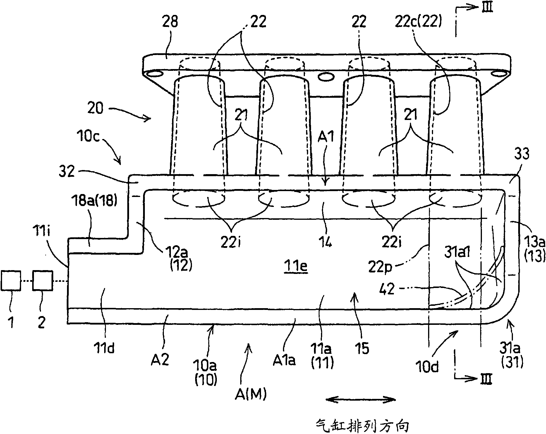
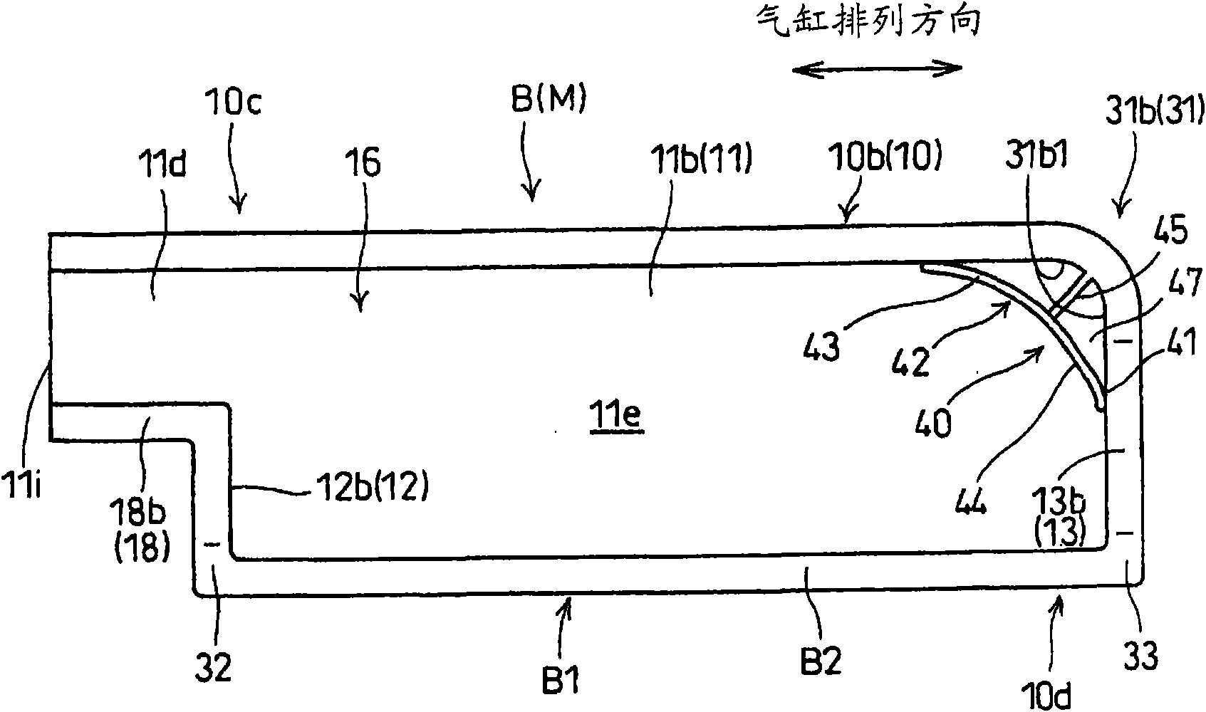
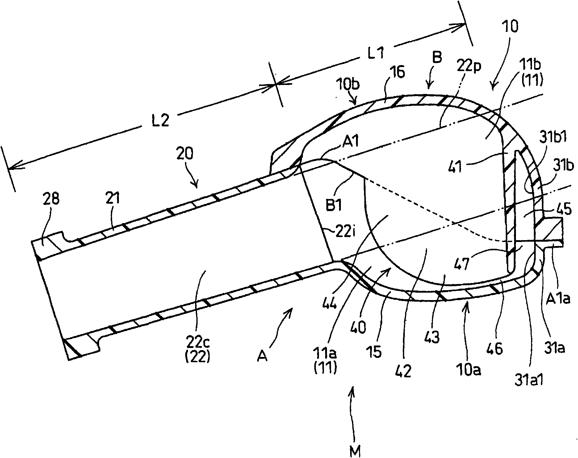
[0019] refer to figure 1 , figure 2 and image 3 , the intake manifold M to which the present invention is applied is provided in an inline four-cylinder internal combustion engine which is a multi-cylinder internal combustion engine mounted on a vehicle. The internal combustion engine has an internal combustion engine main body composed of the following parts: a cylinder block in which a predetermined number (here, four) of cylinders are arranged in line and integrally formed; a cylinder head bonded to the cylinder block; and a cylinder head bonded to the cylinder head on the cylinder head cover.

[0020] Furthermore, the internal combustion engine has a piston reciprocally fitted in each of the cylinders, and is rotatably supported by the cylinder block driven by the pressure of combustion gas generated in the combustion chamber. The crankshaft in the engine is d...


PUM


Abstract

An intake manifold (M) for a multi-cylinder internal combustion engine has a collection section (10) for forming an intake collection chamber (11) and also has a branch section (20) for forming an intake branch path (22). The collection section (10) is formed by joining first and second spaces (11a, 11b), which form the intake collection chamber (11), to first and second cases (A, B).Corners (31a,31b) are formed integrally with the first and second cases (A, B). In the second case (B) is placed a flow straightening section (40) extending across the inside of the first and second cases (A, B)and covering the inner surfaces (31a1, 31b1) of the corners (31a, 31b). The flow straightening section (40) has a guidance surface (44) for more smoothly guiding intake air than the inner surfaces (31a1, 31b1). The flow straightening section (40) and the corners (31a, 31b) together form a rear space (47) communicated with the intake collection chamber (11). The construction smoothens the flow of intake air in the intake collection chamber to improve volumetric efficiency irrespective of the shape of the corners of the intake manifold having a split structure, and in addition, the constructionsuppresses a pressure variation in the intake collection chamber by utilizing the rear space formed by the flow straightening section.

Description

technical field [0001] The present invention relates to an intake manifold of a multi-cylinder internal combustion engine. The intake manifold has a collection part and a branch part. The collection part forms an intake collection chamber. The branch part branches out from the intake collection chamber and forms a A plurality of intake branch paths for introducing intake air to each combustion chamber. Background technique [0002] It is known to provide a guide portion for smoothing the flow of intake air between the intake manifold and the combustion chambers in the intake manifold of a multi-cylinder internal combustion engine (for example, refer to Patent Document 1). [0003] Patent Document 1: Japanese Patent Laid-Open No. 2003-74431 [0004] The intake manifold of a multi-cylinder internal combustion engine has a converging part and a branching part: the converging part forms an intake collecting chamber with an intake inlet, from which the diverging part branches of...

Claims


Application Information

Patent Timeline
Patent Type & Authority Applications(China)
IPC IPC(8): F02M35/10
CPCY02T10/146F02M35/10262F02M35/112F02M35/10098Y02T10/14F02M35/10052F02M35/10354Y02T10/12F02M35/104F02M35/10
Inventor 平贵浩福田昭二郎林正人
Owner HONDA MOTOR CO LTD