Electric switching device

A switchgear, electric switch technology, applied in the direction of electric switches, circuits, electrical components, etc., can solve problems such as changes, unfavorable safety, etc.

Inactive Publication Date: 2010-02-03
SIEMENS AG
View PDF0 Cites 5 Cited by
  • Summary
  • Abstract
  • Description
  • Claims
  • Application Information

AI Technical Summary

Problems solved by technology

In addition, each of the aforementioned factors can lead to changes in tripping performance (i.e. identification and

Method used


Image

  • Electric switching device
  • Electric switching device
  • Electric switching device

Examples


Embodiment Construction

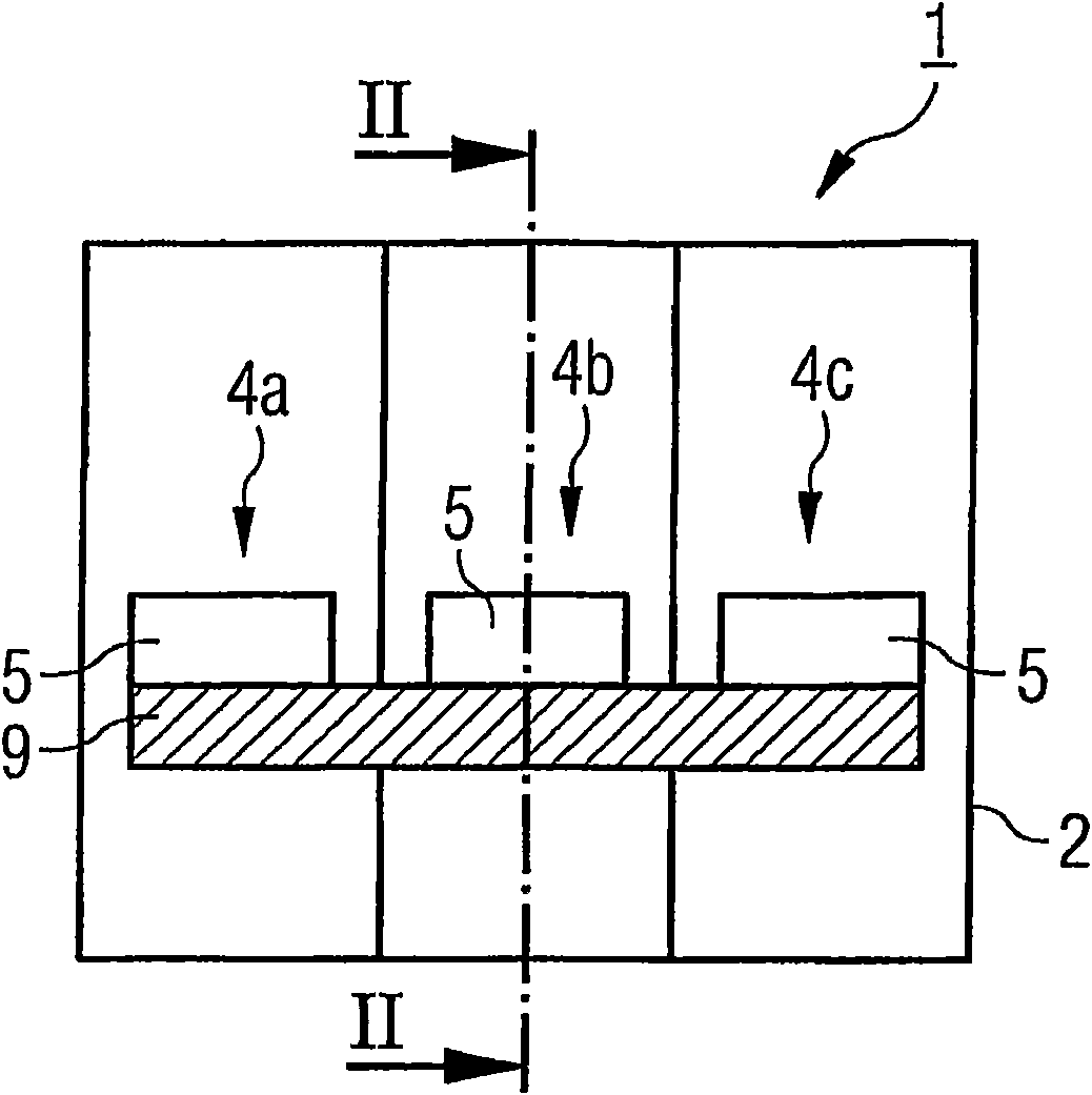
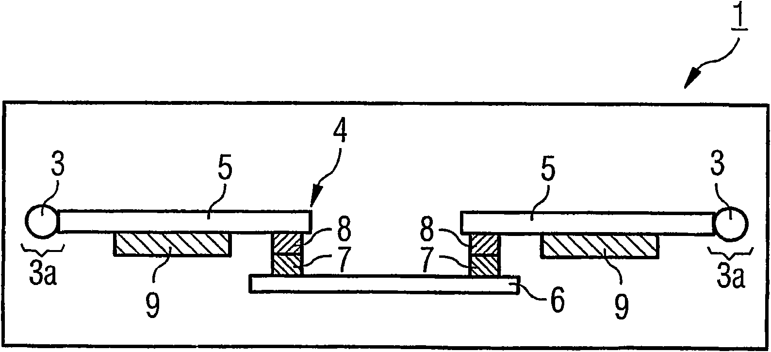
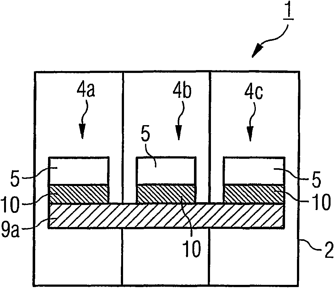
[0019] The switchgear 1 shown only schematically in the figures comprises a housing 2 made of an electrically insulating material, in particular a plastic material. There are a plurality of connecting pieces 3 on the housing 2, such as screw-type connecting pieces, and these connecting pieces can be connected with incoming or outgoing wires. Current paths 4 a , 4 b , 4 c are arranged between these connecting pieces 3 . Each current path comprises two contact carriers 5 , a contact bridge 6 for connecting the two contact carriers, and the connection piece 3 and / or the connection region 3 a. Electrical contacting between the contact bridge 6 and the contact carrier 5 is effected via contact elements 7 , 8 arranged on the contact bridge 6 and / or the contact carrier 5 .

[0020] The switchgear 1 is a three-phase switchgear. Thus, there are three adjacently arranged current paths 4a, 4b and 4c. The contact carriers 5 or connection regions 3 a of these current paths are connected...


PUM


Abstract

The invention relates to an electric switching device having a housing (2) made of electrically insulating material, wherein current paths (4a, 4b, 4c) associated with three different phases of a three-phase system are provided. Said current paths each comprise a contact region (14) with a contact bridge (6), wherein the current paths are thermally connected to each other via at least one thermalbridge (9, 9a, 9b, 9c) made at least partially of a material that has greater thermal conductivity than the material of the housing or than air.

Description

technical field [0001] The invention relates to an electrical switching device having a housing made of electrically insulating material and three current paths arranged in the housing, which are assigned to different phases of a three-phase system . Background technique [0002] In general, each current path is formed by two conductors and / or contact carriers separated from each other in the contact area. A contact bridge is arranged in the contact region, by means of which the two conductors can be electrically connected to one another. The housing of such switching devices consists of electrically insulating material, in most cases plastic. During operation of the switchgear or in the event of a fault in the switchgear (for example overload or short circuit), the power transmission and switching processes generate heat in the switchgear which has to be experienced by the plastic forming the housing. Another reason for uneven heating of the conductors and / or the current...

Claims


Application Information

Patent Timeline
IPC IPC(8): H01H1/62
CPCH01H9/0072H01H1/62H01H9/52
Inventor 马丁·海姆勒安德烈亚斯·克拉奇马赫
Owner SIEMENS AG
Why Eureka
Try Eureka