Improved energy storage device
一种储能装置、充电能力的技术,应用在车辆储能、运输和包装、电容器型半电池和一次或二次半电池等方向,能够解决缩短电池潜在寿命等问题
- Summary
- Abstract
- Description
- Claims
- Application Information
AI Technical Summary
Problems solved by technology
Method used
Image
Examples
Embodiment
[0202] Reference example 1
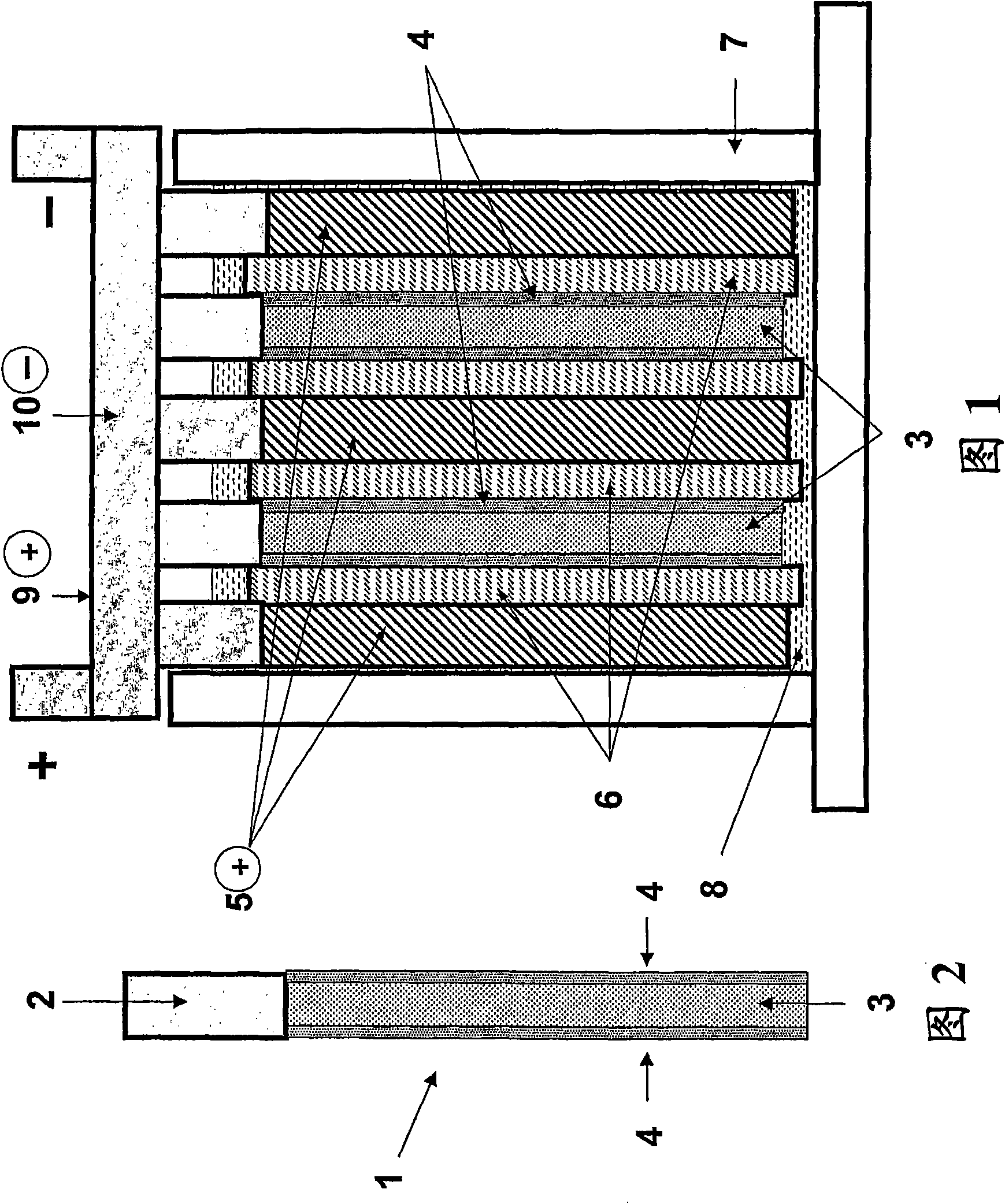
[0203] prepared with such figure 1 and 2 A suitable lead-acid based energy storage device for experimental purposes with the arrangement schematically shown in .
[0204] The device contains two composite negative electrodes (1), and the composite negative electrode (1) contains a current collector (2), and the battery negative electrode material (3) is pasted on the current collector (2). Each face of the electrode material has a coating of capacitor electrode material (4), thereby forming a composite negative electrode. The device also contains a lead dioxide positive electrode (5), which may or may not contain additive materials, depending on the experiment. Positive and negative electrodes such as figure 1 The alternating arrangement shown in is arranged in the battery compartment (7). The lead dioxide positive electrode (5) can be 20-500 mm wide, 20-1200 mm high, and 0.6-5 mm thick. The width and height dimensions of the composite negati...
Embodiment 3
[0228] below and Figure 9 The discharge and charge process of the positive plate and the dissolution of lead sulfate in different concentrations of sulfuric acid solutions are shown in .
[0229] Discharge process:
[0230]
[0231] Charging process:
[0232]
[0233] During discharge, the conversion of lead dioxide to lead sulfate occurs in two steps. First, lead dioxide and HSO at the positive plate 4 - and H + Reaction to form Pb 2+ , SO 4 2- and H 2 O, the so-called "dissolution process" (reaction 1). Then, Pb 2+ with SO 4 2- combined to form PbSO 4 , the so-called "deposition process" or "precipitation process" (reaction 2). The first step is an electrochemical reaction and thus involves electron movement and migration. Electrons enter the positive plate from the opposite (counter) negative plate and move to the reactive site (ie, lead dioxide), where electron transfer occurs. The movement of electrons in the positive plate material occurs through c...
Embodiment 5
[0252] Curve used in the present embodiment and reference example 2 Figure 6 Used similarly. Five cells were constructed with positive and negative plates having the same width and height dimensions (ie, 44 mm wide and 71 mm high) but with different thicknesses, densities, and positive plate material additives. The cells were subjected to the same test procedure as described in Reference Example 2. The test results are in Figure 13 shown in . The conditions (i.e. plate thickness, density, additives) and properties applied to each battery are as follows:
[0253] (i) As shown in curve 51, the thickness of the positive plate of the control battery is 1.55 mm, and the paste density is 4.0 g cm -3 , no additives; the thickness of the negative plate is 1.65mm, and the paste density is 4.1gcm -3 , No capacitor material coating. The battery completed 45,000 cycles and failed due to the performance of the positive plate.
[0254] (ii) As shown in curve 52, the thickness of the ...
PUM
| Property | Measurement | Unit |
|---|---|---|
| density | aaaaa | aaaaa |
| particle diameter | aaaaa | aaaaa |
| diameter | aaaaa | aaaaa |
Abstract
Description
Claims
Application Information
 - R&D
- Intellectual Property
- Life Sciences
- Materials
- Tech Scout
- Unparalleled Data Quality
- Higher Quality Content
- 60% Fewer Hallucinations
Browse by: Latest US Patents, China's latest patents, Technical Efficacy Thesaurus, Application Domain, Technology Topic, Popular Technical Reports.
© 2025 PatSnap. All rights reserved.Legal|Privacy policy|Modern Slavery Act Transparency Statement|Sitemap|About US| Contact US: help@patsnap.com


