Double support pipe cutting equipment

A technology of pipe cutting equipment and double supports, applied in welding equipment, laser welding equipment, metal processing equipment, etc., can solve the problems of low processing efficiency, high installation accuracy requirements, and affecting processing quality, and achieve high processing accuracy and production efficiency. high effect

Inactive Publication Date: 2010-02-10
李路平
View PDF1 Cites 17 Cited by
  • Summary
  • Abstract
  • Description
  • Claims
  • Application Information

AI Technical Summary

Problems solved by technology

Laser processing needs to cut a seam twice to complete. After the first cut, the pipe is rotated and indexed. However, the pipe is long and heavy, and it is prone to deflection. The center position of the pipe is shifted, resulting in laser focus or tool The position relative to the pipe also shifts accordingly, resulting in uneven distribution of the slits in the circumferential direction of the pipe, and quality defects such as overburned seams and oversized dimensions, resulting in unqualified product quality
[0004] 2. The pipe is very long, and the total stroke of the laser cutting head is also very long
Due to the influence of the divergence angle of the laser beam itself, the change of the length of the optical path during the processing will cause the change of the beam diameter, which will affect the processing quality
[0005] 3. The machining stroke of the cutting head along the axis of the pipe is limited, and it is impossible to complete the processing of the entire tube at one time. It is necessary to manually push the tube to be processed many times, making it difficult to accurately and quickly send the tube to the predetermined position
However, the two support devices of this laser processing machine tool are fixedly installed, and the distance cannot be adjusted; and because there is a gap between the automatic feeding device and the support device, it is difficult to ensure that the pipe is aligned with the clamping port of the support device when feeding; even if the pipe is successfully inserted into the first One support device, there is still a long distance between the first support device and the second support device, and the pipe is prone to deflection, which makes it difficult to insert the pipe into the second support device, resulting in low processing efficiency and poor installation accuracy High standard

Method used


Image

  • Double support pipe cutting equipment
  • Double support pipe cutting equipment
  • Double support pipe cutting equipment

Examples


Embodiment Construction

[0025] With reference to accompanying drawing, further illustrate the present invention:

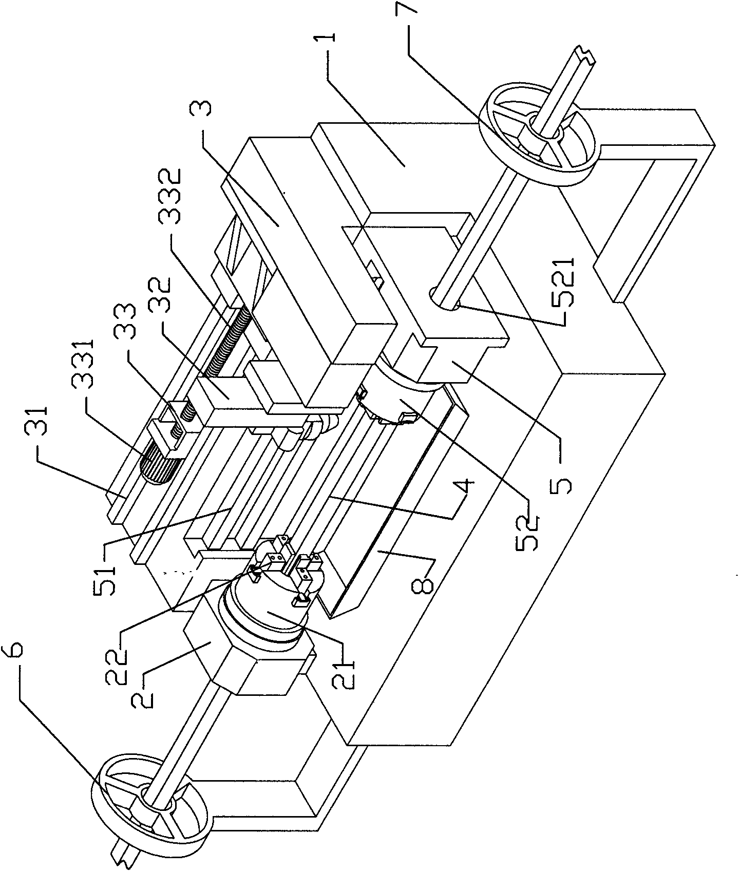
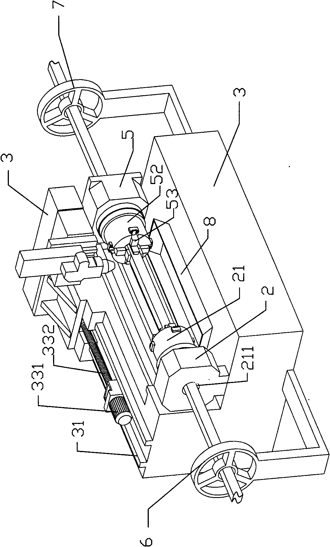
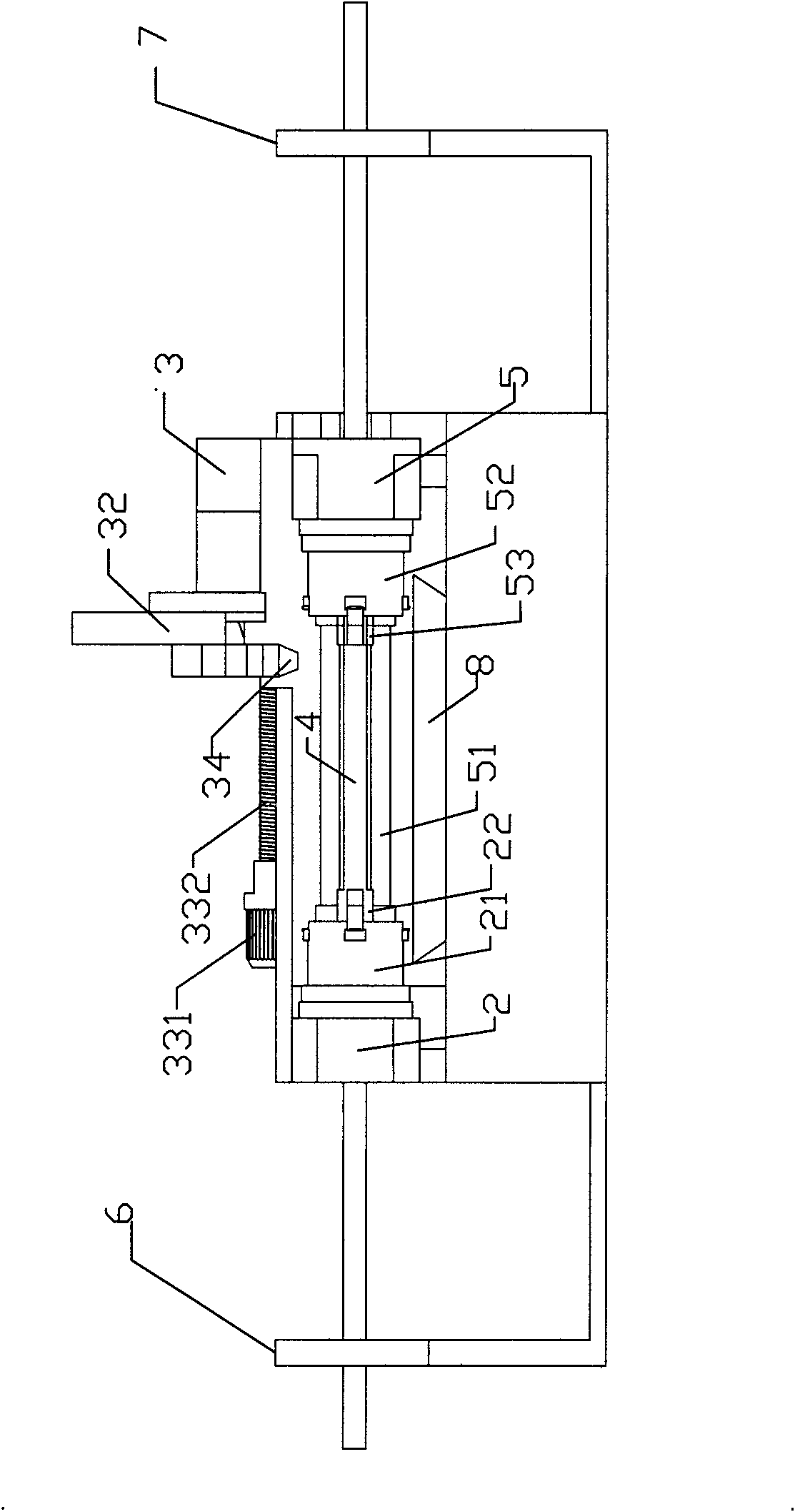
[0026] The double-support pipe cutting equipment includes a frame 1, and the frame 1 is provided with a support mechanism 2 for receiving incoming pipe materials and a cutting mechanism 3 for slitting and processing the pipe 4;

[0027] The support mechanism 2 includes a first support seat 21 fixed on the frame 1 and a first clamp 22 for clamping pipes;

[0028] Described cutting mechanism comprises the cutting guide rail 31 that is fixed on the frame, the cutting support 32 that is slidably installed on the cutting guide rail 31, and the pushing mechanism 33 that promotes cutting support 32 sliding; Described cutting support 32 is equipped with A laser cutting head 34 positioned directly above the pipe material 4;

[0029] The double-support pipe cutting equipment also includes a feeding mechanism 5, and the feeding mechanism 5 includes a feeding guide rail 51 fixed on the machine tool...


PUM


Abstract

The invention relates to a double support pipe cutting equipment, comprising a frame and a feeding mechanism; the frame is provided with a supporting mechanism for bearing incoming materials of the pipe and a cutting mechanism for processing the cutting seams of the pipe; the supporting mechanism comprises a first supporting seat fixed on the frame and a first clamp for clamping the pipe; the cutting mechanism comprises a cutting guide rail, a cutting bracket and a pushing mechanism; the cutting bracket is provided with a laser cutting head positioned above the pipe; the feeding mechanism comprises a feeding guide rail fixed on a machine tool and a second supporting seat arranged on the feeding guide rail in a sliding manner; the supporting seat is provided with a second clamp which is strictly aligned with the first clamp and rotates synchronously with the first clamp; and when the second clamp moves forward and backward, the first clamp and the second clamp alternatively clamp the cut pipe. The double support pipe cutting equipment can keep constant for the central position of the pipe in the processing process, can lead the pipe to be fed automatically, can carry out processingto a whole pipe without pipe waste materials, and has high processing precision and high production efficiency.

Description

technical field [0001] The invention relates to a machine tool for pipe cutting, in particular to a double-support pipe cutting device. Background technique [0002] Existing pipe cutting equipment mainly includes a chuck for clamping pipes and a cutting mechanism (laser cutting or mechanical cutting can be used). When cutting pipes, the following problems are often encountered: [0003] 1. The pipe is long and heavy. Traditional cutting machine tools (whether laser cutting or mechanical cutting) usually clamp one end of the pipe, and the other end is supported by a floating support. Laser processing needs to cut a seam twice to complete. After the first cut, the pipe is rotated and indexed. However, the pipe is long and heavy, and it is prone to deflection. The center position of the pipe is shifted, resulting in laser focus or tool The position relative to the pipe also shifts accordingly, resulting in uneven distribution of the slits in the circumferential direction of t...

Claims


Application Information

Patent Timeline
Patent Type & Authority Applications(China)
IPC IPC(8): B23K26/38B23K26/42B23K26/08B23K101/06
CPCB23K26/38B23K26/0823
Inventor 李路平
Owner 李路平
Why Eureka
Try Eureka