Piston and internal combustion engine of circular slider-crank mechanism

A crank round slider and round slider technology, applied in the directions of pistons, cylindrical pistons, machines/engines, etc., can solve the problems of bulkiness, poor balance performance, bulky internal combustion engines and compressors, etc., to reduce stress and improve bearing capacity. ability, the effect of improving the service life

Inactive Publication Date: 2010-02-10
BEIJING SINOCEP ENGINE TECH
View PDF3 Cites 2 Cited by
  • Summary
  • Abstract
  • Description
  • Claims
  • Application Information

AI Technical Summary

Problems solved by technology

However, in the crank linkage mechanism, due to the existence of the connecting rod, the internal combustion engine and the compressor of the crank linkage mechanism have defects such as bulky, heavy, and poor balance performance.

Method used


Image

  • Piston and internal combustion engine of circular slider-crank mechanism
  • Piston and internal combustion engine of circular slider-crank mechanism
  • Piston and internal combustion engine of circular slider-crank mechanism

Examples


Embodiment 1

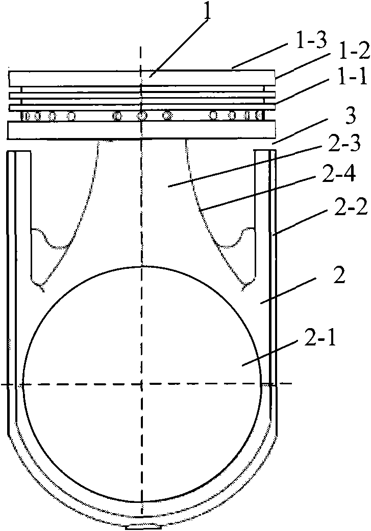
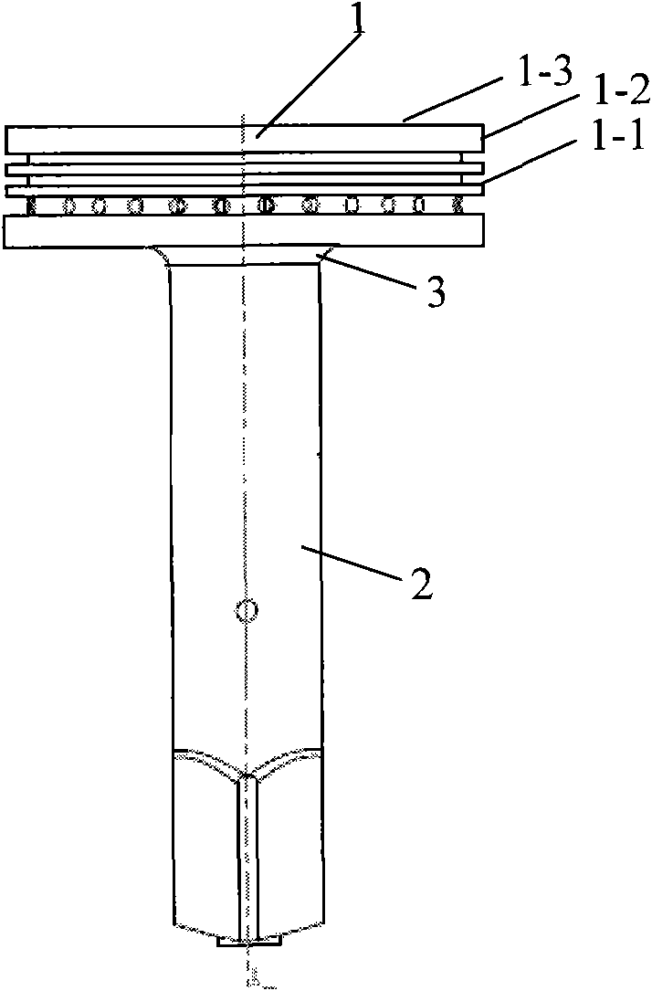
[0035] figure 1 It is the front view of the piston of the slider crank mechanism of the first embodiment of the present invention, figure 2 It is a left side view of the piston of the slider crank mechanism of the first embodiment of the present invention. in, figure 1 and figure 2 Shown in is a single-acting piston, ie a piston crown is provided at only one end of the piston seat. It should be understood that the piston of the present invention may also be a double-acting piston, that is, a piston crown is also provided at the other end of the mounting seat. In this embodiment, only one end of the mounting seat is provided with a piston crown as an example to illustrate the piston of the crank-slider mechanism of the present invention, and the other end of the piston mounting seat can also be the same as or similar to that of the first embodiment of the present invention. An additional crown is provided, forming a double-acting piston.

[0036] Please refer to figure ...

Embodiment 2

[0050] In this embodiment, the strength of the piston crown is enhanced by arranging reinforcing ribs at the bottom of the piston crown. Wherein, the reinforcing ribs may be strip ribs radiating from the center of the bottom of the crown to the periphery. In this embodiment, a cross beam is taken as an example for description. It should be understood that the reinforcing ribs may also be other strip-shaped ribs, such as rice-shaped ribs. Certainly, the reinforcing rib may also be in other shapes, such as a plate shape. It is not described here one by one, and those skilled in the art can set reinforcing ribs of different shapes according to the teaching of the description of the present invention and in combination with actual needs.

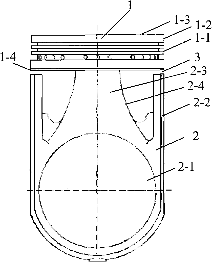
[0051] image 3 It is a front view of the piston of the slider crank mechanism of the second embodiment of the present invention.

[0052] Such as image 3 As shown, the piston of this embodiment includes a piston seat 2 and a crown 1 arran...

Embodiment 3

[0060] Figure 5 It is the front view of the piston of the slider crank mechanism of the third embodiment of the present invention. Figure 6 It is the left side view of the piston of the slider crank mechanism of the third embodiment of the present invention.

[0061] Please refer to Figure 5 and Figure 6 , In the embodiment of the present invention, the piston of the crank-slider mechanism includes a mounting base 2 and a crown 1 . The crown 1 is disposed at one end of the mounting base 2 . The other end of the mounting base 2 can be suspended, or a counterweight insert can be set, and another crown can be installed in the same way as any of the methods in this specification or in other ways to form a double-acting piston.

[0062] Wherein, the crown 1 and the mounting seat 2 can be integrally formed, or can be fixedly assembled together by means of riveting or screwing. In this embodiment, the crown 1 and the mounting base 2 are integrally formed as an example for il...


PUM


Abstract

The invention discloses a piston of a circular slider-crank mechanism, comprising a piston seat and a crown arranged at one end of the piston seat, wherein, a circular slider containing hole and a lateral guide plate are arranged on the piston seat; the crown comprises an annular zone; the lateral guide plate is arranged along the profile of the piston seat; thermal resistance gap is arranged between the lateral guide plate and the annular zone. The piston can prevent the heat of the crown from being transferred to the lateral guide plate of the piston seat or decrease the heat when an internal combustion engine works, thus decreasing expansion and deformation of the lateral guide plate of the piston seat due to heat. The invention also provides the internal combustion engine comprising the piston of the circular slider-crank mechanism.

Description

technical field [0001] The invention relates to a piston, in particular to a piston of a crank circular slider mechanism. The invention also relates to an internal combustion engine. Background technique [0002] In a traditional internal combustion engine, the reciprocating motion of the piston is converted into the rotational motion of the crankshaft through the crank-link mechanism, and then the crankshaft drives the corresponding moving parts to output power externally. However, in the crank-link mechanism, due to the existence of the connecting rod, the internal combustion engine and the compressor of the crank-link mechanism have defects such as bulky, heavy, and poor balance performance. [0003] In order to solve the above problems, the Chinese patent with the date of examination and approval announcement as January 13, 1988 and the announcement number as CN85200358B discloses a "crank circular slider reciprocating piston internal combustion engine"; the date of aut...

Claims


Application Information

Patent Timeline
Patent Type & Authority Applications(China)
IPC IPC(8): F16J1/00F02F3/00
Inventor 黎明黎正中
Owner BEIJING SINOCEP ENGINE TECH
Why Eureka
Try Eureka