
Method of machining a work piece with a focused particle beam

A technology for processing workpieces, particle beams, used in material analysis using wave/particle radiation, preparation of samples for testing, electrical components, etc., which can solve problems such as expensive modifications, inability to reliably produce high-quality samples, and complex instrumentation.

Inactive Publication Date: 2010-02-10
FEI CO
View PDF4 Cites 8 Cited by
  • Summary
  • Abstract
  • Description
  • Claims
  • Application Information

AI Technical Summary

Problems solved by technology

[0013] The problem with this partial solution is that oxidation occurs even at low (incomplete) pressures such as oxygen or water, so that storing or shipping samples by this method does not reliably yield high quality samples
At the same time, the costs associated with this part of the solution (including the addition of a vacuum-tight interface between the transport unit and the FIB and / or TEM) will result in complex and expensive retrofitting of the instruments used

Method used


Image

  • Method of machining a work piece with a focused particle beam
  • Method of machining a work piece with a focused particle beam
  • Method of machining a work piece with a focused particle beam

Examples


Embodiment Construction

[0038] Figure 1a , 1b and 1c schematically show the formation of thinned flakes for inspection in TEM.

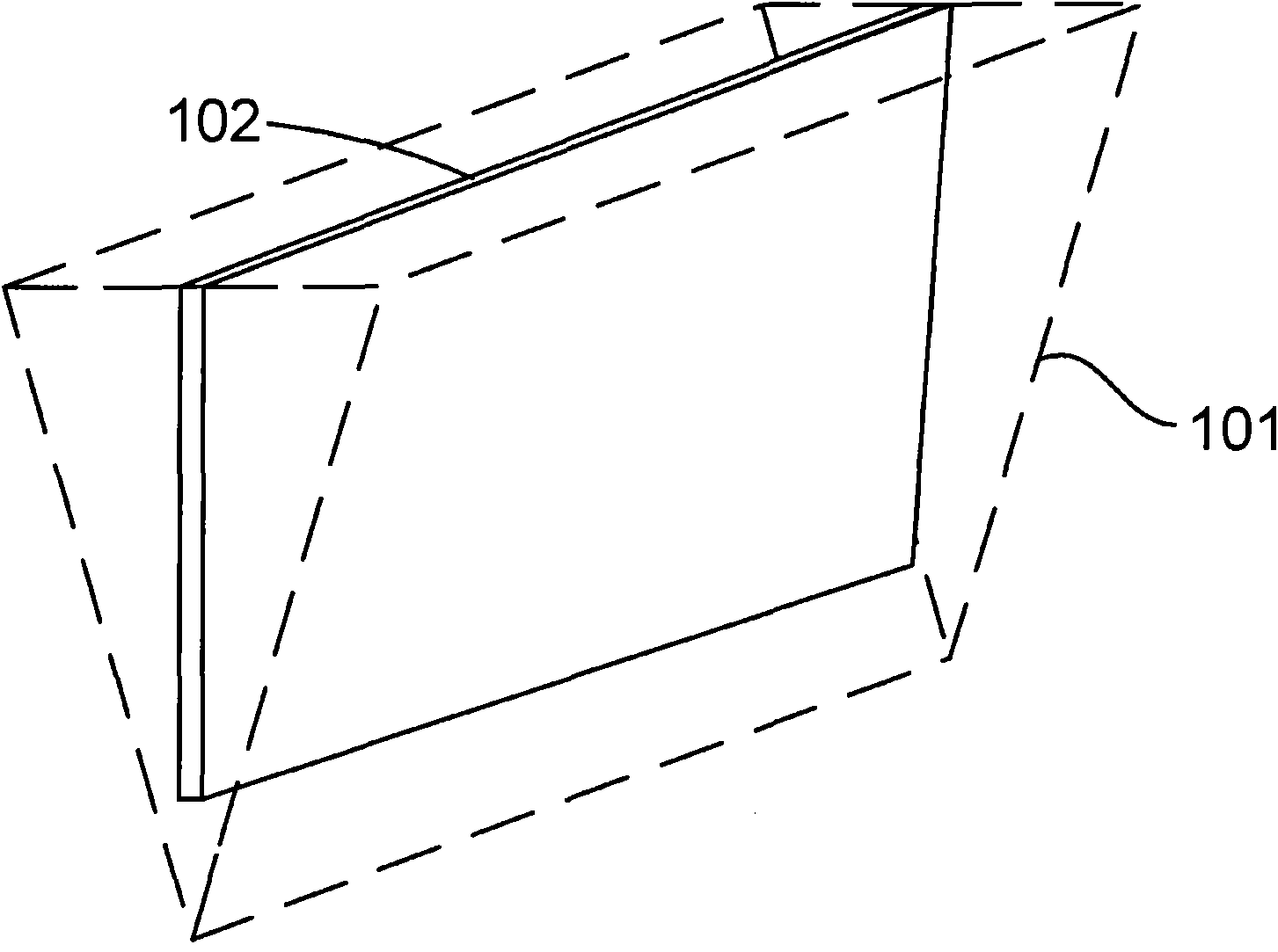
[0039] Figure 1a Wedges and lamellas taken from workpieces are schematically shown. A wedge 101 of, for example, semiconductor material breaks away from a workpiece (eg, a wafer). The wedge is then thinned into a thin sheet 102 . Usually the flakes are still too thick to be used as TEM samples.

[0040] It should be noted that the wedge may take the form of a thick sheet.

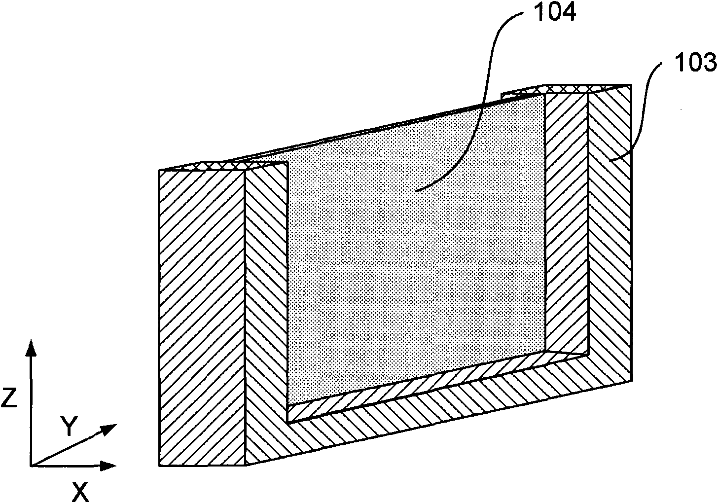
[0041] Figure 1b A thick lamella 102 detached earlier is schematically shown to be locally thinned to form a sample with relatively strong edges 103 and thin film 104 . Film 104 typically has a final thickness of less than 50 nm, although films having a thickness of, for example, 100 nm or greater may be used for some applications.

[0042] Grinding is preferably accomplished with an ion beam scanned across the surface of the lamella at an oblique angle, ie in a direction parallel to or close to...


PUM


Abstract

The invention relates to a method of machining a work piece with a focused particle beam. The invention relates to a method for producing high-quality samples for e.g. TEM inspection. When thinning samples with e.g. a Focused Ion Beam apparatus (FIB), the sample often oxidizes when taken from the FIB due to the exposure to air. This results in low-quality samples, that may be unfit for further analysis. By forming a passivation layer, preferably a hydrogen passivation layer, on the sample in situ , that is: before taking the sample from the FIB, high quality samples are obtained.

Description

technical field [0001] The present invention relates to a method of processing a workpiece with a focused particle beam to form a sample, the method comprising: [0002] inserting said workpiece into a particle-optical device, [0003] processing the workpiece by exposing the workpiece to a focused particle beam to form the sample, [0004] • Removing the sample from the particle-optical device. [0005] Such a method is known from US Patent No. US 5,270,552. Background technique [0006] For examination of samples in a transmission electron microscope (TEM), for example samples taken from semiconductor wafers, samples with a thickness of less than 100 nm and preferably with a thickness of less than 50 nm are routinely used. [0007] Known methods disclose forming a sample from a workpiece, such as a semiconductor wafer, by first inserting the wafer into a focused ion beam device (FIB). Wedges or flakes of material are formed by grinding grooves with a focused ion beam a...

Claims


Application Information

Patent Timeline
Patent Type & Authority Applications(China)
IPC IPC(8): G01N1/32G01N23/04G01N23/203
CPCH01J37/317G01N1/32H01J37/3178G01N1/286H01J2237/31745
Inventor J·J·L·穆尔德斯A·P·J·M·博特曼B·H·弗赖塔格
Owner FEI CO
Learn More