Capacitive acceleration sensor with acoustic cavity

An acceleration sensor and acceleration technology, applied in the field of inertial sensors, can solve the problems of high vacuum degree requirements of devices, gas cannot flow to other places, complex elastic behavior, etc., to achieve easy adjustment of Q value, easy to restore work, and simple elastic behavior. Effect

Inactive Publication Date: 2010-02-10
INST OF ACOUSTICS CHINESE ACAD OF SCI
View PDF1 Cites 55 Cited by
  • Summary
  • Abstract
  • Description
  • Claims
  • Application Information

AI Technical Summary

Problems solved by technology

Although these two structures have commercial products, they have high requirements on the vacuum degree in the device, and the mass block is relatively small. The quality factor Q of the system often depends on the vacuum degree inside the acceleration, which often limits the vacuum degree in other aspects. Applications
Moreover, in the above two structures, there is a close

Method used


Image

  • Capacitive acceleration sensor with acoustic cavity
  • Capacitive acceleration sensor with acoustic cavity
  • Capacitive acceleration sensor with acoustic cavity

Examples


Embodiment 1

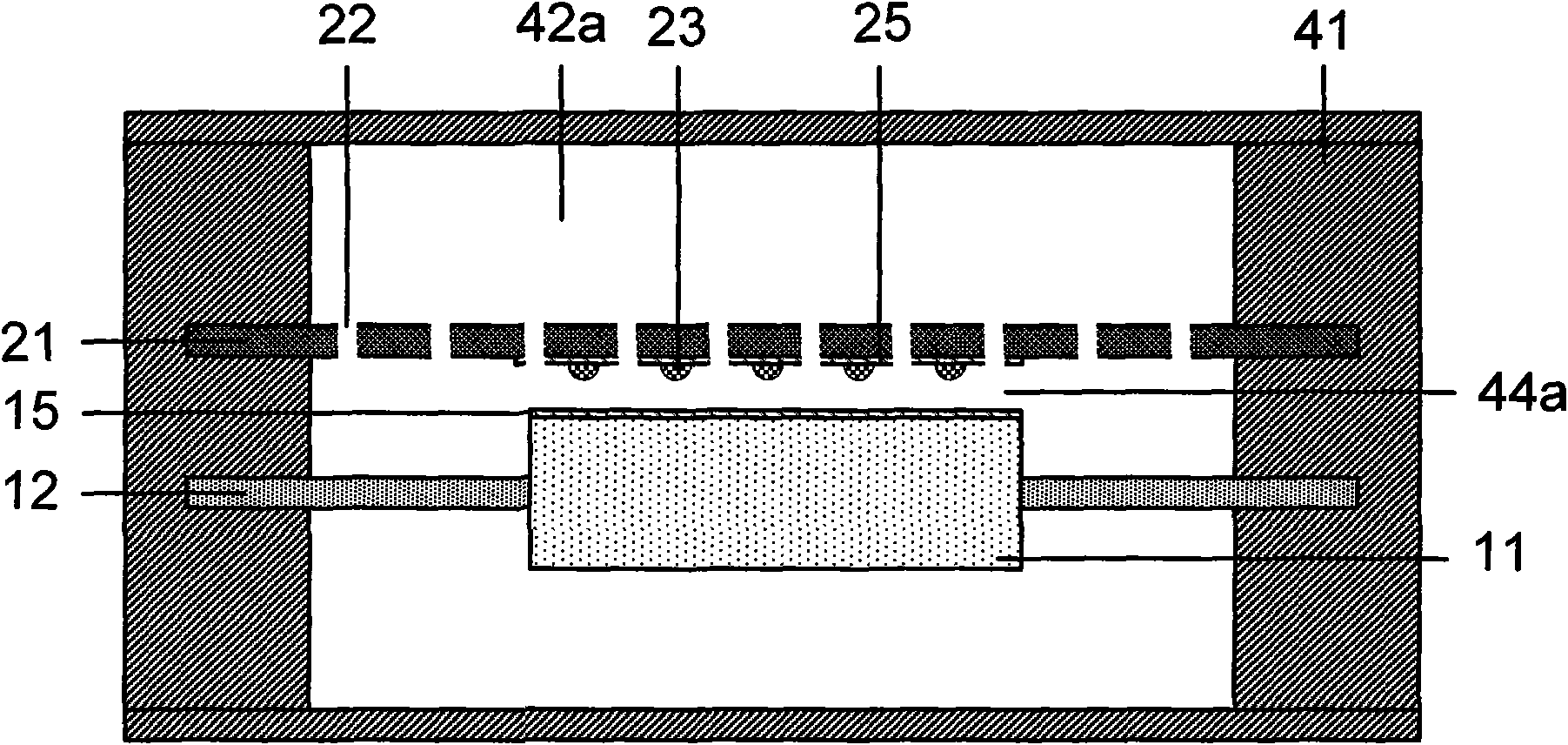
[0057] figure 1 It is a cross-sectional view of one of the embodiments of the capacitive acceleration sensor with an acoustic cavity of the present invention, which has a structure of a back plate. Such as figure 1 As shown, a capacitive acceleration sensor provided in this embodiment includes: an acceleration detection structure 10 composed of a proof mass 11 and an elastic vibrating membrane 12, and a back plate 21 with a damping hole 22 and a limit bump 23. , and the acceleration sensor frame 41.

[0058] In a plane perpendicular to the direction of motion, the detection mass 11 is located at the center of the sensor, and its boundary is connected to the inner boundary of the elastic vibrating membrane 12, and the elastic vibrating membrane 12 is located at the periphery of the detection mass 11, and its outer boundary is connected to the inner boundary of the sensor frame 41. The inner boundaries are connected. Both the detection mass 11 and the elastic vibrating membra...

Embodiment 2

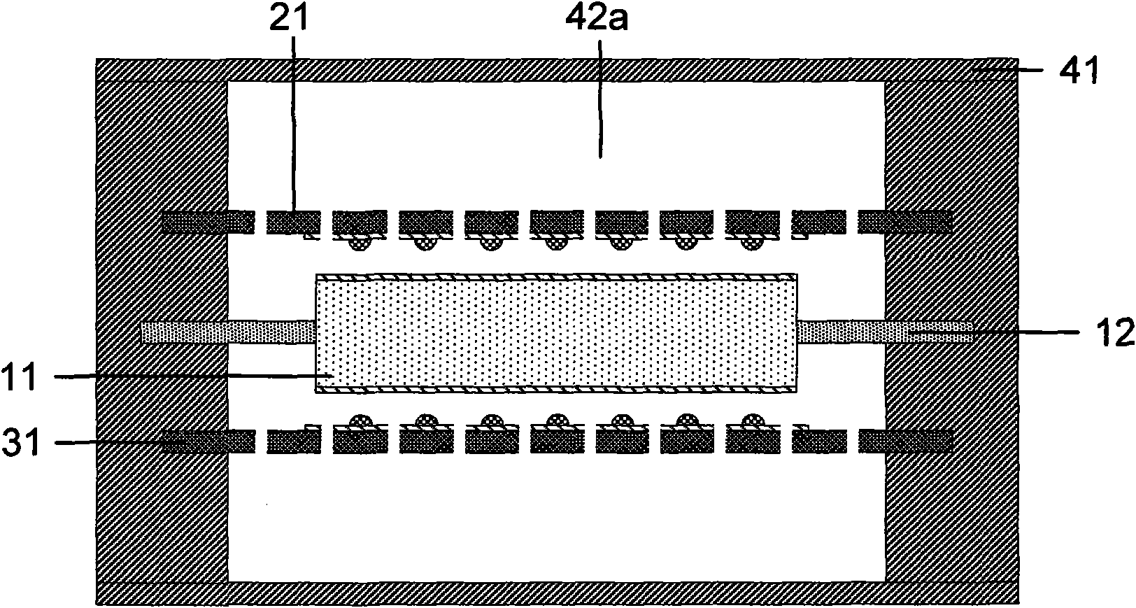
[0065] figure 2 It is a cross-sectional view of one of the embodiments of the capacitive acceleration sensor with an acoustic cavity of the present invention, which has a structure of two back plates. Such as figure 2 As shown, the capacitive acceleration sensor of this embodiment includes: an acceleration detection structure 10 composed of a proof mass 11 and an elastic diaphragm 12; two back plates 21 and 31; and an acceleration sensor frame 41 and other structures. Wherein, the mass block 11, the vibrating membrane 12, the back pole plate 21 and the back pole plate 31 are installed in the sensor frame 41, and the space between the upper and lower back pole plates 21 and the frame 41 formed after sealing The cavity and the cavity between the back plate 31 and the frame 41 are the acoustic cavity 42a and the acoustic cavity 42b.

[0066] In a plane perpendicular to the direction of motion, the detection mass 11 is located at the center of the sensor, and its boundary is c...

Embodiment 3

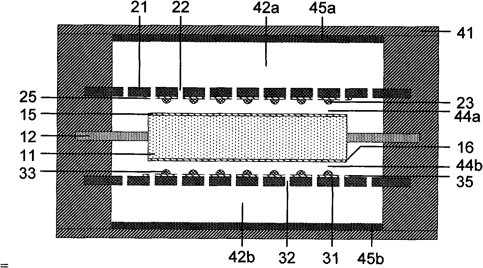
[0073] Figure 4 It is a sectional view of a damping hole structure on the mass block of one of the embodiments of the capacitive acceleration sensor with an acoustic cavity of the present invention. Such as Figure 4 As shown, the capacitive acceleration sensor provided in this embodiment includes: a detection mass 11 , an elastic diaphragm 12 , back plates 21 and 31 , and an acceleration sensor frame 41 .

[0074] In a plane perpendicular to the moving direction, the detection mass 11 and the elastic vibrating membrane 12 are both centrosymmetric figures, and both have the same center of symmetry. The detection mass 11 is located at the center of the sensor, and its boundary is connected to the inner boundary of the elastic diaphragm 12 , and the elastic diaphragm 12 is located at the periphery of the detection mass 11 , and its outer boundary is connected to the inner boundary of the sensor frame 41 .

[0075]In order to further reduce system damping and adjust system par...


PUM

PropertyMeasurementUnit
Thicknessaaaaaaaaaa
Thicknessaaaaaaaaaa

Abstract

The invention provides a capacitive acceleration sensor with an acoustic cavity, comprising a sensor frame, an acceleration detection structure composed of a detection quality block and an elastic vibrating diaphragm, and a back plate with damping holes and limit embosses, wherein, the detection quality block is arranged at the center of the acceleration sensor and is connected with the sensor frame by the surrounding elastic vibrating diaphragm; the damping holes manufactured on the back plate are used for adjusting system damping, and the limit embosses are used for preventing adhesion or damage in the case of overload; the detection quality block is parallel to the back plate, and detection capacitances are respectively formed on the opposite surfaces of the detection quality block andthe back plate; and the fact that the sensor frame is internally provided with an acceleration detection structure and internally formed with the acoustic cavity after the back plate is closed can improve frequency response. The sensor structure of the invention has lower requirement on the vacuum degree of the acceleration sensor, and can adjust important parameters such as a quality factor Q andthe like which can adjust a system by changing density and size of the damping holes and volume of the acoustic cavity and the like, thus realizing larger flexibility on design and manufacture.

Description

technical field [0001] The invention relates to the technical field of inertial sensors, in particular, the invention relates to a novel capacitive acceleration sensor structure with an acoustic cavity. Background technique [0002] Acceleration sensor is a very important inertial sensing and measurement device, which is widely used in aerospace, vibration monitoring, industrial control, geophysical exploration and other fields. In recent years, with the development and maturity of MEMS (micro-electromechanical systems) technology, MEMS acceleration sensors have been widely used in automotive electronics and consumer electronics products due to their small size, light weight, low cost, and high integration. And further expand to the field of industrial application, has a broad market prospect. [0003] The acceleration sensor realizes the measurement of the external acceleration by converting the sensed acceleration into an electrical signal output at a certain ratio. Acco...

Claims


Application Information

Patent Timeline
IPC IPC(8): G01P15/125G01P15/097B81B7/02
Inventor 乔东海何庆索智群齐敏游庆瑜
Owner INST OF ACOUSTICS CHINESE ACAD OF SCI
Why Eureka
Try Eureka