
Quasi-resonant controlled switch voltage stabilizing circuit and method

A quasi-resonant control, switching voltage regulation technology, applied in control/regulating systems, electrical components, regulating electrical variables, etc., can solve the problems of switching frequency jumps, audio noise, etc., to avoid switching frequency jumps, prevent audio effect of noise

Active Publication Date: 2010-02-10
CHENGDU MONOLITHIC POWER SYST
View PDF3 Cites 23 Cited by
  • Summary
  • Abstract
  • Description
  • Claims
  • Application Information

AI Technical Summary

Problems solved by technology

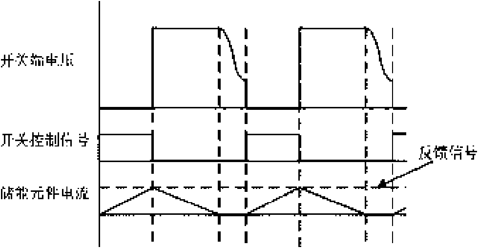
It can be seen from the above that even if the load and input remain unchanged, due to the existence of disturbances in the system, the switch off time will also change, such changes will cause the switching frequency to jump within a few switching cycles, resulting in audio noise

Method used


Image

  • Quasi-resonant controlled switch voltage stabilizing circuit and method
  • Quasi-resonant controlled switch voltage stabilizing circuit and method
  • Quasi-resonant controlled switch voltage stabilizing circuit and method

Examples


Embodiment Construction

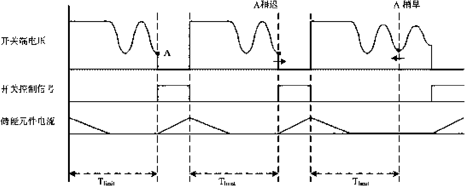
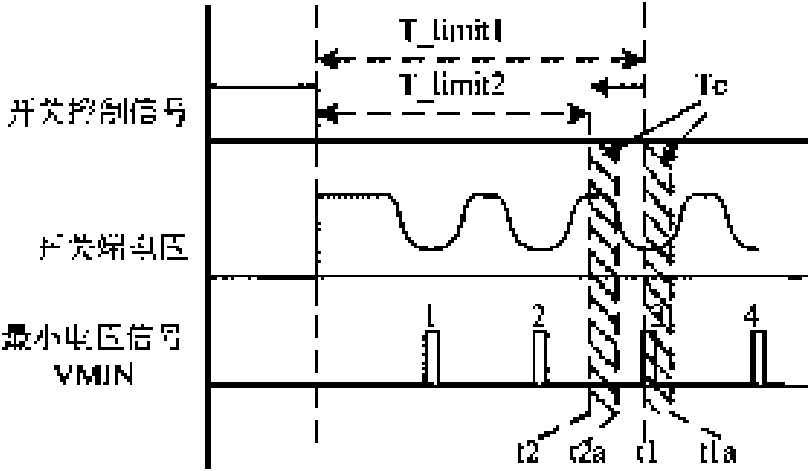
[0018] The invention discloses a quasi-resonance control switching voltage stabilizing circuit and method. The switching frequency is limited by setting a minimum limiting time (minimum switching cycle or minimum off time), and the switch can only be turned on after the minimum limiting time. When the moment of the minimum voltage is close to the end point of the minimum limit time, change the minimum limit time, so as to maintain a sufficient margin between the moment of the minimum voltage and the end point of the minimum limit time, and avoid disturbances in the system that cause switching frequency fluctuations transitions to prevent the generation of audio noise.

[0019] Specific embodiments of the present invention will be described in detail below, and it should be noted that the embodiments described here are only for illustration, not for limiting the present invention.

[0020] Figure 3A with Figure 3B It is a waveform diagram of a quasi-resonant control switchi...


PUM


Abstract

The invention discloses a quasi-resonant controlled switch voltage stabilizing circuit and a method. By setting minimum limit time, a switching frequency is limited, and the minimum limit time is changed when the time of minimum voltage is close to the terminal time of the minimum limit time so that the purpose of preventing audio-frequency noise can be achieved. The circuit thereof comprises an energy storage element, a switch, a control circuit and a frequency limit circuit, wherein the energy storage element can store energy; the switch is electrically coupled with the energy storage element; when the switch is turned on, the energy storage element stores energy; when the switch is turned off, the energy stored in the energy storage element is transferred to the load; the control circuit is electrically coupled with the switch, controls the switch to be turned on or turned off, and turns on the switch when resonant voltage on both sides of the switch are lowered to minimum voltage;and the frequency limit circuit is electrically coupled with the control circuit, and limits the switching frequency of the switch by setting the minimum limit time, wherein when the time of the minimum voltage is close to the terminal time of the minimum limit time, the frequency limit circuit changes the minimum limit time.

Description

technical field [0001] The invention relates to a switching voltage stabilizing circuit, in particular to a quasi-resonance controlled switching voltage stabilizing circuit. Background technique [0002] Many electronic devices today require DC voltage to be powered, and this DC supply voltage usually comes from an adapter. The adapter obtains AC voltage from the wall socket (grid), converts the AC voltage into an uncontrolled DC voltage through a rectifier bridge, and converts the uncontrolled DC voltage into the required DC power supply voltage through a switching power supply. [0003] Switching power supplies usually use transformers or inductors as energy storage elements. For example, a transformer is used as an energy storage element in a flyback converter. A switch is electrically coupled to the primary side of the transformer, and the control circuit controls the switch to be turned on and off, so that energy is alternately stored or transmitted in the transformer....

Claims


Application Information

Patent Timeline
IPC IPC(8): H02M3/335
CPCY02B70/1425H02M3/1563H02M3/33515H02M3/338Y02B70/1433Y02B70/10
Inventor 张军明任远程胡进路环宇石洋
Owner CHENGDU MONOLITHIC POWER SYST
Learn More