Exhaust gas purification apparatus for internal combustion engine

A technology of exhaust purification device and internal combustion engine, which is applied in the direction of exhaust device, internal combustion piston engine, exhaust gas treatment, etc., and can solve the problems that urea is difficult and cannot be effectively prevented

Inactive Publication Date: 2010-02-10
TOYOTA JIDOSHA KK
View PDF2 Cites 4 Cited by
  • Summary
  • Abstract
  • Description
  • Claims
  • Application Information

AI Technical Summary

Problems solved by technology

However, it is difficult to accurately determine the amount of urea stored in the catalyst
In either case, there is a problem that a large amount of substances derived from urea cannot be reliably prevented from being discharged from the catalyst.
If the amount of urea aqueous solution supplied to the catalyst is reduced, a large amount of urea can be prevented from being stored in the catalyst, but in this case, there is a concern that NO can not be reduced well. x

Method used


Image

  • Exhaust gas purification apparatus for internal combustion engine
  • Exhaust gas purification apparatus for internal combustion engine
  • Exhaust gas purification apparatus for internal combustion engine

Examples


Embodiment Construction

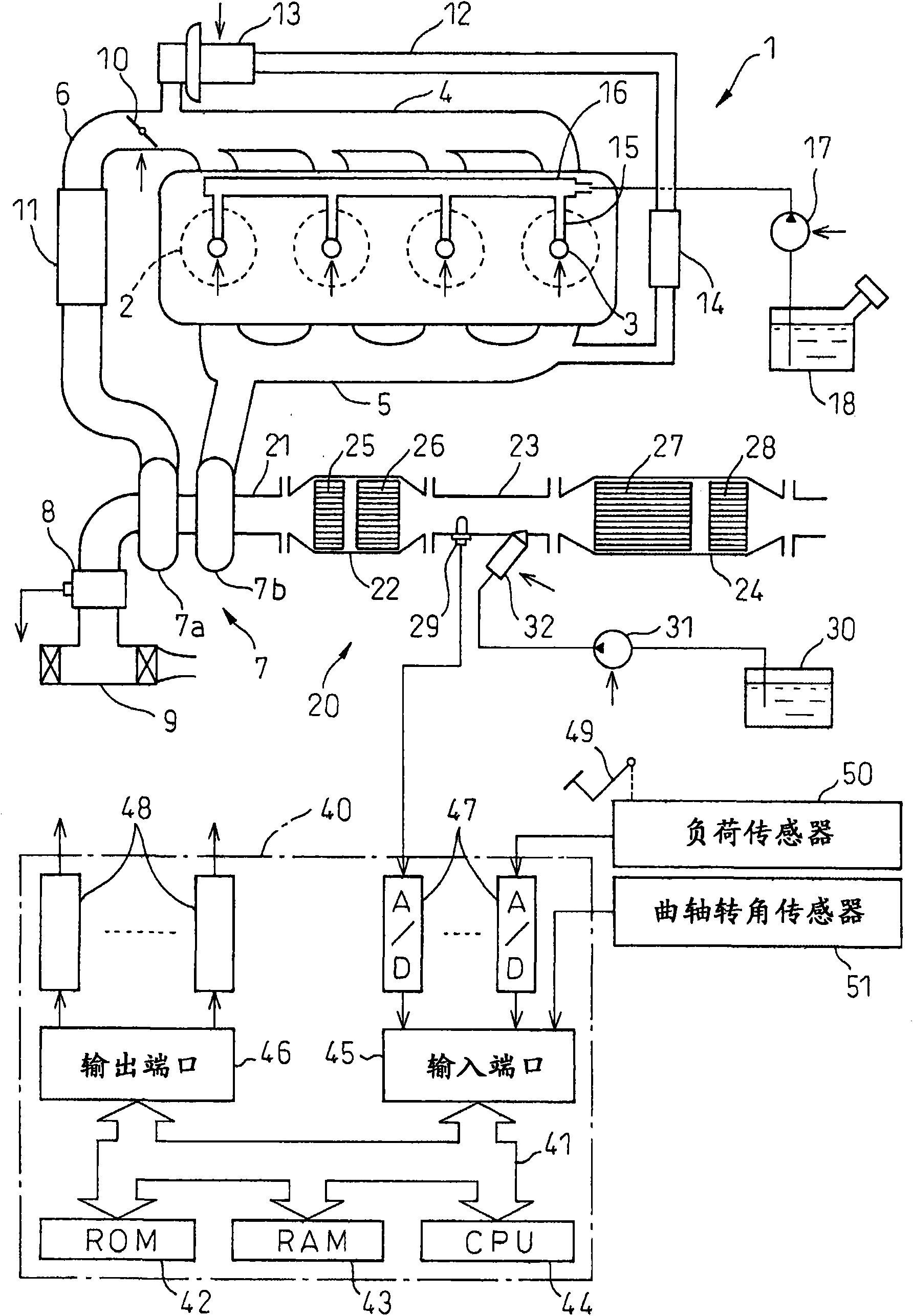
[0008] figure 1 A case where the present invention is applied to a compression ignition internal combustion engine is shown. In addition, the present invention is also applicable to gasoline internal combustion engines.

[0009] refer to figure 1 , and each label is respectively indicated as follows: 1-main body of internal combustion engine, 2-combustion chamber of each cylinder, 3-electronically controlled fuel injection valve for injecting fuel into each combustion chamber 2, 4-intake manifold, 5- exhaust manifold. The intake manifold 4 is connected to an outlet of a compressor 7 a of an exhaust turbocharger 7 via an intake duct 6 , and an inlet of the compressor 7 a is connected to an air cleaner 9 via an air flow meter 8 . An electrically controlled throttle valve 10 is disposed in the intake duct 6 , and a cooling device 11 for cooling intake air flowing in the intake duct 6 is disposed around the intake duct 6 . exist figure 1 In the exemplary embodiment shown, eng...


PUM


Abstract

A catalyst (27) suitable for the reduction of an NOx in an exhaust gas with ammonia in an oxygen-excess atmosphere is placed in an engine exhaust passage. An aqueous urea solution is supplied to the catalyst (27) through a supply control valve (32) to store a part of urea supplied to the catalyst (27) in the inside of the catalyst (27) and reduce the NOx contained in the exhaust gas with ammonia produced from urea stored in the catalyst (27). It is determined whether or not the storage volume of the catalyst (27) is larger than a predetermined allowable upper limit volume. The supply of the aqueous urea solution is stopped when the storage volume of the catalyst (27) is determined to be larger than the allowable upper limit volume.

Description

technical field [0001] The present invention relates to an exhaust purification device for an internal combustion engine. Background technique [0002] There is known an internal combustion engine, which is arranged in the exhaust passage of the internal combustion engine suitable for the reduction of NO in the exhaust gas by ammonia under conditions of excess oxygen. x urea solution is supplied to the catalyst, a part of the urea supplied to the catalyst is stored in the catalyst, and NO in the exhaust gas is reduced by ammonia generated from the urea stored in the catalyst x (Refer to US Patent No. 5,628,186 specification and International Patent Publication No. 99 / 67511). [0003] In this internal combustion engine, part of the urea supplied to the catalyst is temporarily stored in the catalyst, and ammonia, a substance derived from (derived from) urea, is produced from the stored urea. Part of this urea-derived substance is used to reduce NO x , the remainder is not u...

Claims


Application Information

Patent Timeline
Patent Type & Authority Applications(China)
IPC IPC(8): F01N3/08B01D53/94F01N3/20F01N3/28
CPCF01N3/2073B01D2258/014B01D53/9495F01N2610/146F01N13/02F01N2013/026F01N3/106B01D2251/2067F01N3/035F01N2560/06Y02T10/24B01D53/9409F01N3/206B01D53/9477F01N2900/1402F01N3/208F01N2900/1622F01N2610/02F01N13/009F01N13/0097Y02T10/12
Inventor 利冈俊祐小田富久伊藤和浩
Owner TOYOTA JIDOSHA KK
Why Eureka
Try Eureka