High-pressure pump for delivering fuel with an improved design of the bearing arrangement for the support of the cam shaft

A high-pressure pump and camshaft technology, applied in the direction of fuel injection pump, charging system, fuel injection device, etc., can solve the problems such as the inability to guarantee the plane contact of the thrust bearing disc, the failure of the welding seam, the failure of the high-pressure pump, etc.

Inactive Publication Date: 2010-02-10
ROBERT BOSCH GMBH
View PDF0 Cites 8 Cited by
  • Summary
  • Abstract
  • Description
  • Claims
  • Application Information

AI Technical Summary

Problems solved by technology

[0004] Problems arise with this type of mounting of the camshaft in high-pressure pumps, that is, the planar contact of the thrust bearing disc on the planar contact surface in the pump body cannot be guaranteed, because the elastic deformation of the thrust bearing disc is limited by the axial support of the camshaft. cannot be sustained under axial load
This can lead to very high loads on the weld seam between the thrust bearing disk and the radial bearing bush, so that the weld seam can fail
Fracture of the weld seam between the thrust bearing disk and the radial bearing bush is formed as a consequence of the failure, so that this will lead to failure of the high pressure pump

Method used


Image

  • High-pressure pump for delivering fuel with an improved design of the bearing arrangement for the support of the cam shaft
  • High-pressure pump for delivering fuel with an improved design of the bearing arrangement for the support of the cam shaft
  • High-pressure pump for delivering fuel with an improved design of the bearing arrangement for the support of the cam shaft

Examples


Embodiment Construction

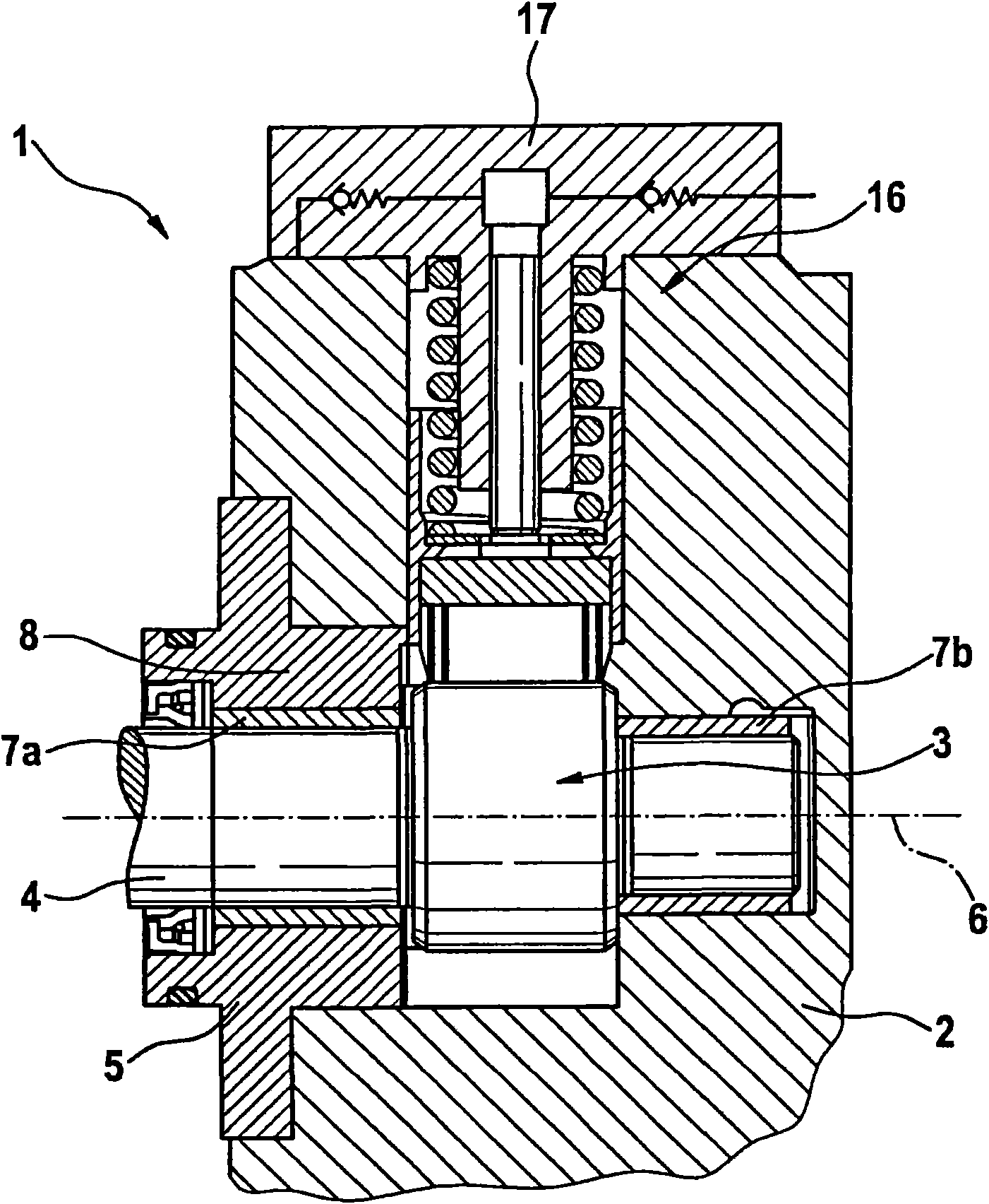
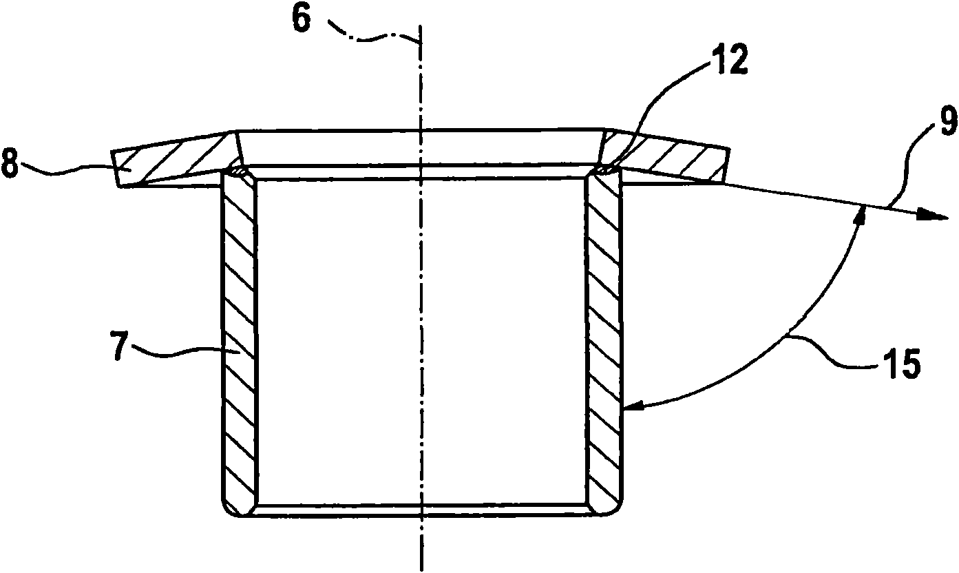
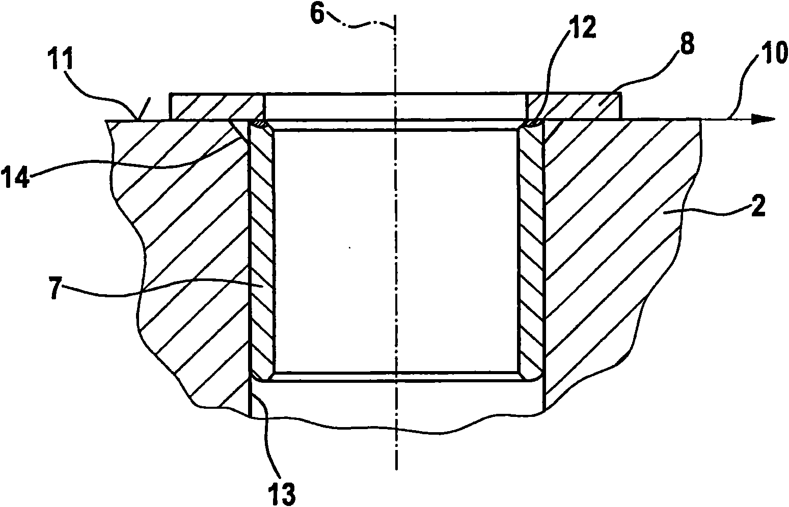
[0019] figure 1 The high-pressure pump 1 shown in includes a pump body 2 in which a camshaft 4 is rotatably mounted in the direction of a camshaft axis 6 . The camshaft 4 includes a cam drive 3 which reciprocates a plunger unit 16 so that it can cooperate with a valve unit 17 for delivering fuel. The support of the camshaft 4 is realized by two supporting devices, that is, a first radial bearing bush 7a arranged on the left side of the cam driving device is installed in a flange body 5, and a second radial bearing bush 7a is installed in a flange body 5. The sleeve 7b is mounted on the right in the pump body 2 itself. There is therefore a radial bearing both on the left and on the right of the cam drive 3, wherein on the left there is a thrust bearing disk 8 which is welded to the radial bearing bushing 7a. Thrust bearing disk 8 serves to absorb forces acting axially in the direction of camshaft axis 6 , which are introduced into camshaft 4 either from the outside or via the...


PUM


Abstract

The present invention relates to a high-pressure pump (1), particularly for delivering fuel for a common rail fuel injection system, comprising a pump body (2), in which at least one cam drive (3) having a cam shaft (4) is received, wherein said cam shaft is pivotally supported about a cam shaft axis (6) in the pump body (2) and / or in a flange body (5) by means of at least one bearing arrangement,and wherein the bearing arrangement comprises a radial bearing bush (7) extending in the direction of the cam shaft axis (6), and an axial bearing disk (8), which is integrally formed on the radial bearing bush (7) on an end, and / or is connected to the same, wherein the axial bearing disk (8) extends in a radial extension direction (9) of <90 DEG relative to the cam shaft axis (6) in the non-installed state, wherein the radial extension direction (9) is directed toward the radial bearing bush (7) and can be brought into an axial bearing plane (10) extending at an angle of 90 to the cam shaft axis (6) in the installed state by means of elastic deformation of the axial bearing disk (8).

Description

technical field [0001] The invention relates to a high-pressure pump for delivering fuel for a common rail fuel injection system of the type specified in the preamble of the claims. Background technique [0002] High-pressure pumps of the type of interest here for delivering fuel are preferably designed with a cam drive, so that the camshaft is rotatably mounted in the pump body and / or in a flange mounted in the pump body. When the high-pressure pump is working, the camshaft rotates around the camshaft axis and reciprocates the push rod unit, which cooperates with a valve unit to deliver fuel. Due to the high operating pressure of the common rail fuel injection system, high forces act on the camshaft via the cam drive. This force is received by sliding bearings arranged on the left and right sides of the cam drive, these sliding bearings comprise radial bearing bushes for receiving radial forces, in which there is a thrust bearing disc, the The push bearing plate receives ...

Claims


Application Information

Patent Timeline
Patent Type & Authority Applications(China)
IPC IPC(8): F02M59/10F02M59/44F02M59/48F04B1/04
CPCF02M59/102F04B1/0404F02M59/48F02M59/44
Inventor G·迈尔A·默茨A·杜特
Owner ROBERT BOSCH GMBH
Why Eureka
Try Eureka