Slurry suction type mineral flotation machine and application thereof

A flotation machine and mineral technology, applied in the direction of flotation, solid separation, etc., can solve the problems such as the full combination of difficult minerals and air bubbles, the unsmooth beneficiation process, and the unstable process indicators. The effect of increased spacing

Inactive Publication Date: 2010-02-17
CHINA NAT OFFSHORE OIL CORP +2
View PDF0 Cites 9 Cited by
  • Summary
  • Abstract
  • Description
  • Claims
  • Application Information

AI Technical Summary

Problems solved by technology

This structure is easy to cause the bubbles to be too large and too fast for collophosite, and because the impeller blades are too large, the stirring intensity is too strong, it is not easy to fully combine the minerals with the bubbles, the foam volume is large, the foam stability is strong, and it is not easy to break, resulting in foam. Difficult transportation, unsmooth beneficiation process, unstable process indicators

Method used


Image

  • Slurry suction type mineral flotation machine and application thereof
  • Slurry suction type mineral flotation machine and application thereof
  • Slurry suction type mineral flotation machine and application thereof

Examples


Embodiment 1

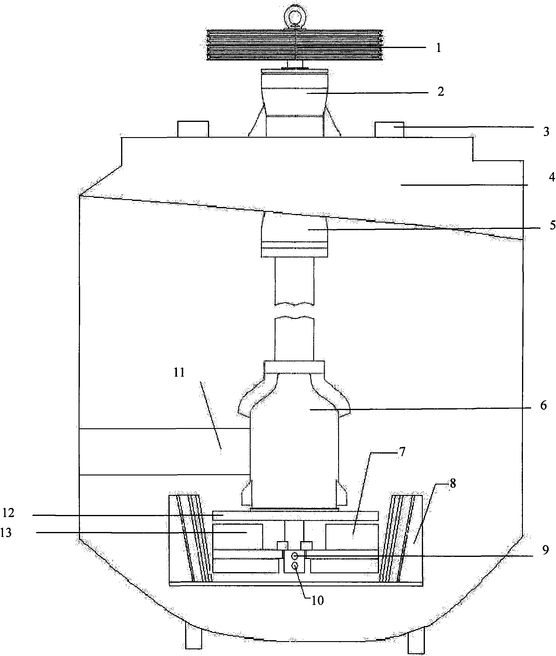
[0027] The structure diagram of the slurry suction mineral flotation machine is as follows: figure 2 As shown, among them, 1 is the large pulley, 2 is the upper bearing body, 3 is the air duct, 4 is the artesian outlet, 5 is the lower bearing body, 6 is the semi-central cylinder, 7 is the rotor impeller, 8 is the stator, 9 is the counter Valve stop float, 10 is an air distributor, 11 is a slurry suction pipeline, 12 is an impeller cover plate, and 13 is a main shaft.

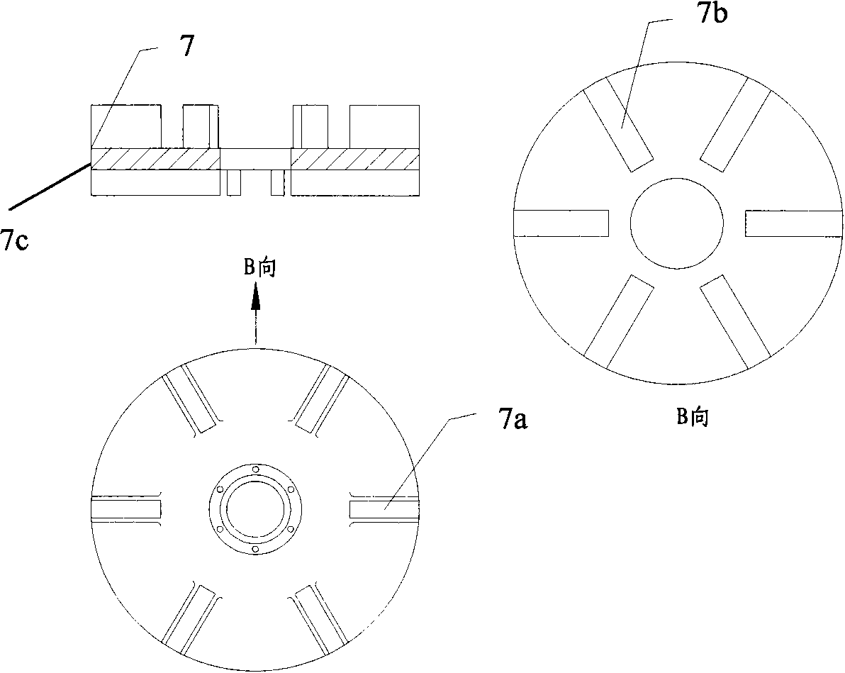
[0028] The flotation machine includes a cavity ( figure 2 Not marked in) and the main shaft 13 located at the center of the cavity and the bearing body that supports the main shaft and is installed concentrically with the main shaft, the bearing body is composed of an upper bearing body 2 and a lower bearing body 5; wherein, the flotation The machine also includes coaxial installation with the main shaft and consists of an impeller cover plate 12, an upper suction blade 7a located under the impeller cover pla...


PUM


Abstract

The invention discloses a slurry suction type mineral flotation machine and application thereof. The flotation machine comprises a cavity body, a spindle arranged in the center of the cavity body, a bearing body, a rotor impeller, a stator, an air distributor, a slurry suction pipeline and a check valve floating ball, wherein the bearing body is used for supporting the spindle, and the bearing body and the spindle are concentrically installed; the rotor impeller and the spindle are coaxially installed, and the rotor impeller comprises an impeller cover plate, an upper slurry suction blade arranged below the impeller cover plate, a substrate arranged below the upper slurry suction blade and a lower part stirring dispersion blade arranged below the substrate; the stator is arranged at the periphery of the rotor impeller and is concentrically installed with the spindle to be fixed on a groove body; the air distributor is connected with the substrate of the rotor impeller , is coaxially installed with the spindle and is a cylindrical part with an opening arranged on the surface; the slurry suction pipeline is connected with the cavity body and extends to the external of the cavity body; and the check valve floating ball is arranged in the air distributor. The flotation machine has low energy consumption and little abrasion, and can remarkably enhance the mineral separation efficiency to cause a mineral separation flow to be smoother.

Description

technical field [0001] The invention relates to a slurry-suction type mineral flotation machine for collophosite beneficiation. Background technique [0002] For a long time, the flotation machine used in the collophosite beneficiation field has been using the traditional method, which is composed of a main shaft, an impeller, a stator, a bearing body, a tank body, a scraper system, an air distribution system and a slurry suction pipe. When the impeller rotates, the slurry in the tank is sucked into the blades of the impeller from the bottom of the tank from all sides, at the same time, the low-pressure air is fed by the blower, enters the air distributor of the impeller cavity through the hollow shaft, and passes through the small hole of the air distributor. , into the impeller blades. The pulp and air are fully mixed between the blades of the impeller and discharged from the upper part of the impeller. This structure is easy to cause the bubbles to be too large and too ...

Claims


Application Information

Patent Timeline
Patent Type & Authority Applications(China)
IPC IPC(8): B03D1/16B03D1/24
Inventor 傅克文王维民孙景山孙立田郭文平刘一鸣杨腾驹于思海沈立新宋瑞峰周长福
Owner CHINA NAT OFFSHORE OIL CORP
Why Eureka
Try Eureka