
Wing-added hole-expanding pile and wing-added hole expander

A technology of reaming piles and reamers, which is applied to sheet pile walls, earthmoving machines/shovels, construction, etc., can solve the problems of difficulty in giving full play to the potential of foundation soil, small application range and high cost of pile foundations. Simple structure, improved single pile uplift resistance, good matching effect

Inactive Publication Date: 2010-02-17
张继红
View PDF0 Cites 6 Cited by
  • Summary
  • Abstract
  • Description
  • Claims
  • Application Information

AI Technical Summary

Problems solved by technology

Among them, bored piles, prefabricated piles, and cast-in-place piles have basically constant diameter along the pile length direction. Therefore, in terms of single pile bearing capacity, especially the provided pullout bearing capacity is mainly based on lateral resistance, so the The bearing capacity provided is small, and it is difficult to give full play to the potential of the foundation soil. Foundation piles such as expanded bottom piles, rammed piles, bamboo piles and other foundation piles have been improved in the end resistance of the pile body, and can form external The expansion part can improve the bearing capacity of a single pile, but the external expansion part formed by the current reaming technology is completed by drilling, rotary excavation and other forms of construction. After forming, the outer contour of the section of the expanded pile section is a convex curve. Afterwards, the hole is easy to collapse, and the diameter of the reaming hole is small. Therefore, although this type of pile has been used, the application range is small, and the cost of the pile foundation is still high.

Method used


Image

  • Wing-added hole-expanding pile and wing-added hole expander
  • Wing-added hole-expanding pile and wing-added hole expander
  • Wing-added hole-expanding pile and wing-added hole expander

Examples


Embodiment Construction

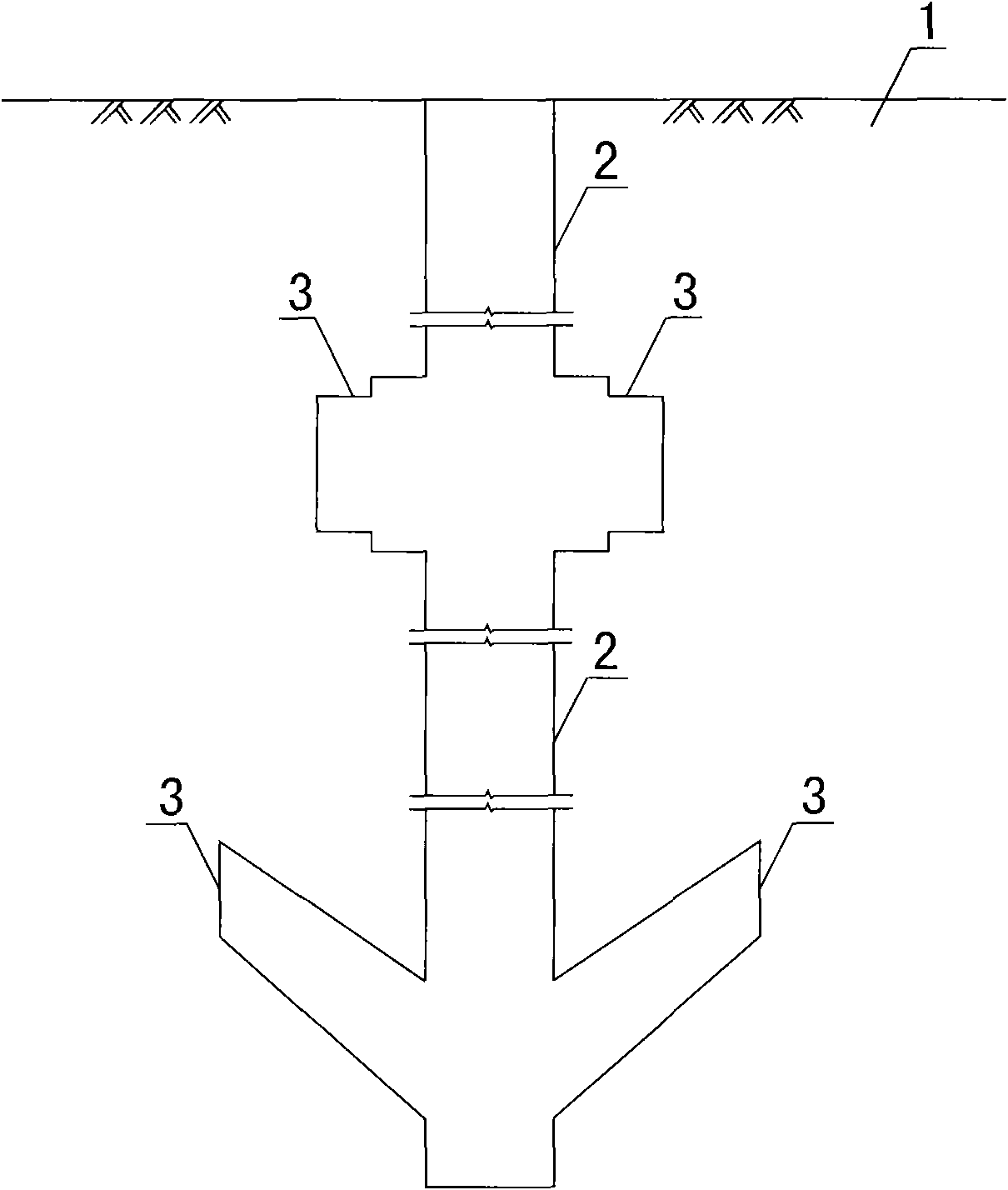
[0020] As an embodiment of the wing-increasing reaming pile and the used wing-increasing reamer of the present invention, holes are first drilled at the pile position to form the pile hole before the reaming construction, and then such as Figure 4 The first type of wing-enhancing reamer shown is placed in the position to be reamed along the pile hole, and its direction is as follows: Figure 4 The shown first type of wing reamer positioning oil cylinder 4 is filled with high-pressure liquid, so that the shrinkage is as follows: Figure 4 The wing-increasing piston rod 5 of the first type of wing-increasing hole reamer positioning oil cylinder 4 shown in the first type stretches out, and inserts such as figure 1 In the rock and soil mass 1 around the shown pile hole, it can be Figure 4 The shown first type wing-increasing reamer wing-increasing piston rod 5 is set as a multi-stage piston rod to increase the reaming range. Figure 4 The shown first type wing-increasing reame...


PUM


Abstract

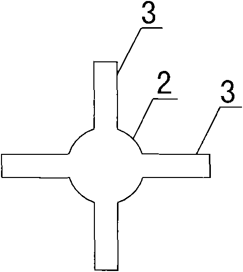
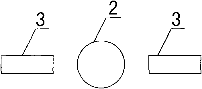
The invention provides a wing-added hole-expanding pile and a wing-added hole expander. The wing-added hole-expanding pile can be added with stiffening wings (3) in a rock-soil mass (1) along a pile body (2). After hole-expanding construction is completed, the outer contour line of the section of the hole-expanding section pile is a concave curve or a combination of not less than two closed curves; large-scale hole-expanding construction around and on the bottom of the pile can be realized; holes are not easy to collapse after the hole-expanding construction; few pile-body materials are neededfor filling expanded holes; and a compact solid pile body can be formed after the hole-expanding construction is completed. Therefore, the anti-pulling / anti-compression bearing capacity of single pile can be greatly improved, and cost for pile foundation is saved. Compared with the prior hole-expanding equipment, the wing-added hole expander used in the construction of the wing-added hole-expanding pile has great improvement. The wing-added hole expander has the advantages of producing no slurry in a hole-expanding process and greatly reducing engineering cost for anti-pulling / anti-compression devices in geotechnical engineering, along with simple structure, high hole-expanding efficiency, good matching property with the prior piling machinery and capability of repeated use.

Description

technical field [0001] The invention relates to the field of civil engineering, in particular to an engineering pile form in anti-pull and anti-compression engineering. Background technique [0002] The pullout and compression piles in existing projects mainly include bored cast-in-place piles, prefabricated piles, immersed pipe cast-in-place piles, bottom-expanded cast-in-place piles, rammed and expanded piles, and bamboo-jointed piles. Among them, bored piles, prefabricated piles, and cast-in-place piles have basically constant diameter along the pile length direction. Therefore, in terms of single pile bearing capacity, especially the provided pullout bearing capacity is mainly based on lateral resistance, so the The bearing capacity provided is small, and it is difficult to give full play to the potential of the foundation soil. Foundation piles such as expanded bottom piles, rammed piles, bamboo piles and other foundation piles have been improved in the end resistance o...

Claims


Application Information

Patent Timeline
IPC IPC(8): E02D5/36E02D5/48E02F5/16
Inventor 张继红
Owner 张继红
Learn More