
Highway deceleration strip generating set

A technology for power generation devices and speed bumps, which is applied to machines/engines, mechanical equipment, mechanisms for generating mechanical power, etc., can solve the problems of increasing the production cost of speed bumps, high costs, and constraints, and achieve improved energy utilization and connection methods Unique, Simple Effects

Inactive Publication Date: 2011-06-15
CHINA AGRI UNIV
View PDF0 Cites 0 Cited by
  • Summary
  • Abstract
  • Description
  • Claims
  • Application Information

AI Technical Summary

Problems solved by technology

[0007] 1. All parts need to be placed inside the speed bump, which is difficult to realize
As we all know, the lower volume space of the speed bump is very small. There are two ways to install complex components. One is to increase the volume of the speed bump, which will not only have an adverse effect on the car's overturning, but also increase the production cost of the speed bump; Larger reconstruction of the road will increase the damage to the road, and the cost will be higher, which restricts the application of this type of invention
[0008] 2. The energy after the car crosses the deceleration belt every time cannot be stored and reused, but directly drives the mechanical equipment to the generator for power generation
In addition, according to the working characteristics of the generator, short working time and small driving energy cannot generate reliable electricity, and the generator works too frequently, especially in places where there are many cars, which seriously affects the use of the generator life

Method used


Image

  • Highway deceleration strip generating set
  • Highway deceleration strip generating set
  • Highway deceleration strip generating set

Examples


Embodiment Construction

[0018] The present invention will be described in detail below in conjunction with the accompanying drawings and embodiments.

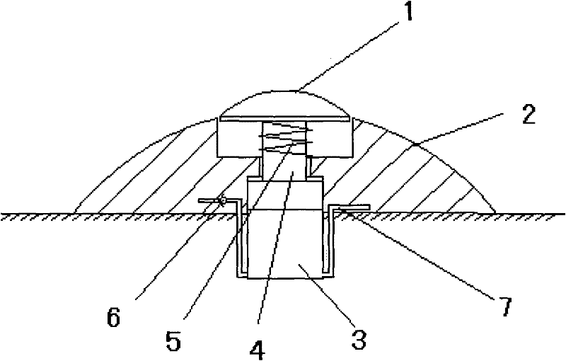
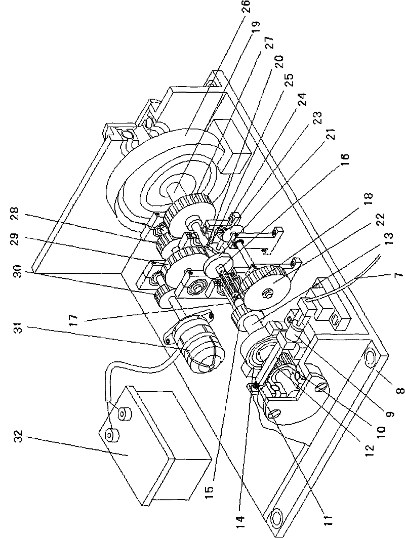
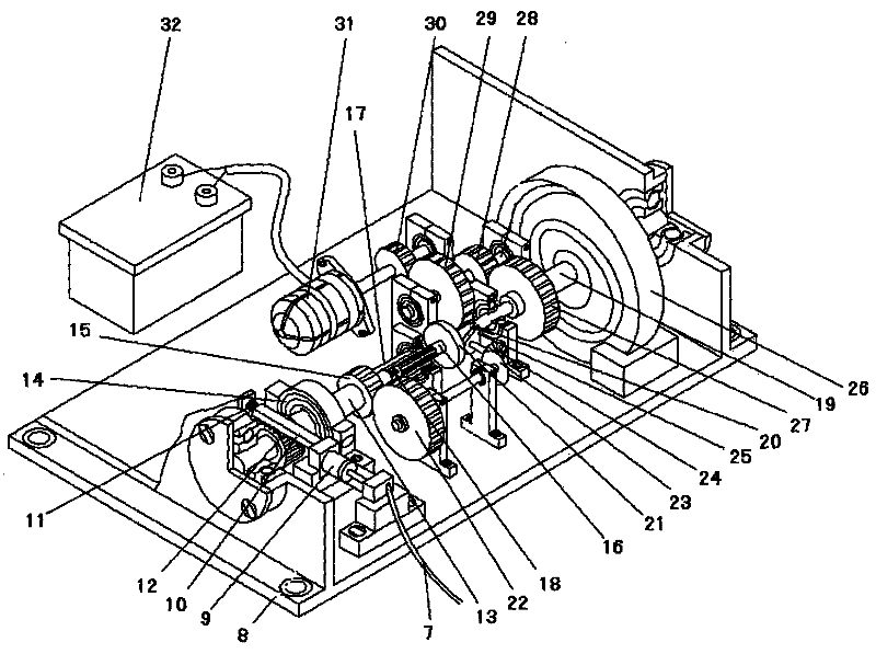
[0019] The present invention consists of figure 1 The pavement section shown and as figure 2 The host section shown consists of two parts.

[0020] The function of the road surface is to convert the mechanical energy of the car into compressed air and transmit it to the host part. The road surface part is mainly composed of a pressure body 1, a deceleration belt 2 and a cylinder group. The cylinder group includes a cylinder 3, a piston 4, a return spring 5, an air intake pipeline 6 and an air outlet pipeline 7, etc. Its specific structure is as follows: figure 1 Shown:

[0021] There is a groove on the upper surface of the speed bump 2, and the cylinder group is embedded in the speed bump 2, wherein the upper end of the piston 4 protrudes from the cylinder 3 and is exposed in the groove. The top of the piston 4 is connected with a pressure body 1...


PUM


Abstract

The invention relates to a highway deceleration strip generating set comprising a road surface part and a host part, wherein the road surface part comprises a deceleration strip and a cylinder group in the deceleration strip. A piston of the cylinder group is connected with a pressed body, the pressed body is higher than the deceleration strip, and the cylinder group is also connected with an airinlet pipeline and an air outlet pipeline; the air outlet pipeline is connected to a single-action cylinder of the host part; the single-action cylinder drives a rack, and the rack is joggled with a unidirectional force transferring gear sleeved on a first shaft; the first shaft is also provided with an unidirectional clutch and a pair of joggled reduction gears; reduction gear shafts are connected with a pair of bevel gears joggled in 90 degrees, and bevel gear shafts are connected with a cam; the first shaft is connected with a second shaft through a spline and a spring, and the second shaft is sheathed with a push disc touching the cam; the second shaft is connected with a third shaft through a jack clutch mechanism; the third shaft is sheathed with a plane volute spring and a unidirectional force transferring acceleration gear; the unidirectional acceleration gear is connected to a generator through a multiple-stage acceleration gear; and the generator is connected to a storage battery. The generating set occupies small area of a road surface and can continuously store energy.

Description

technical field [0001] The invention relates to a power generation device, in particular to a power generation device for a road deceleration belt. Background technique [0002] According to the data released by the National Bureau of Statistics, as of the end of 2008, the number of civil vehicles in my country reached 64.67 million, and the number of vehicles is growing at a high speed, while traffic accidents have also remained high. In order to slow down high-speed vehicles on some special road sections and reduce the occurrence of traffic accidents, a large number of deceleration belts are set up in residential areas, toll stations, urban-rural junctions, and some accident-prone areas on national and provincial roads to protect pedestrians and roads. vehicle safety. When the car climbs over the speed bump, a certain amount of energy will be generated due to its own weight. If this energy is not collected, it will become useless and wasted; if the energy of each car is c...

Claims


Application Information

Patent Timeline
Patent Type & Authority Patents(China)
IPC IPC(8): F03G7/00
Inventor 赵建柱马煜赵曾武马锃宏
Owner CHINA AGRI UNIV
Learn More