Force balance type electric cylinder featuring fluid circulation

A technology of fluid circulation and force balance, applied in the direction of fluid pressure actuation devices, etc., can solve the problems of waste of resource costs, unbalanced positive and negative torque output of electric cylinder motors, etc., achieve cost reduction, increase work reliability, and improve service life Effect

Active Publication Date: 2010-02-17
无锡智航控制技术有限公司
View PDF0 Cites 15 Cited by
  • Summary
  • Abstract
  • Description
  • Claims
  • Application Information

AI Technical Summary

Problems solved by technology

[0004] In the application field of electric cylinder with axial compression load, the positive and negative torque output of the electric cylinder motor is unbalanced. If the average output torque in the positive direction is more than twice the average output torque in the negative direction, the user often chooses a large-load motor to solve the problem, but it will bring The problem of waste of resources and costs

Method used


Image

  • Force balance type electric cylinder featuring fluid circulation

Examples


Embodiment Construction

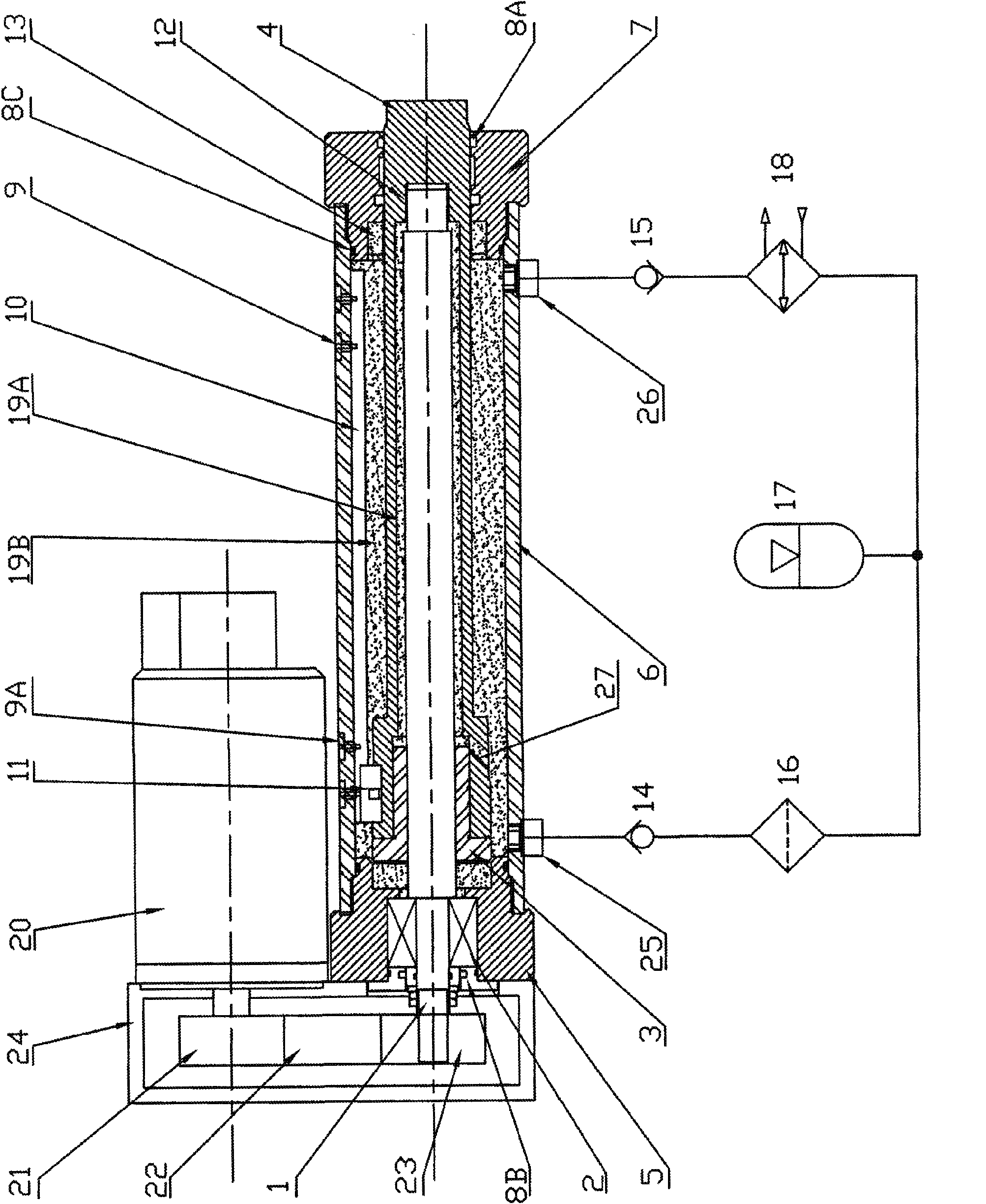
[0016] The force balance fluid circulation electric cylinder of the present invention will be further described below in conjunction with the accompanying drawings.

[0017] A force-balanced fluid circulation electric cylinder, including a machine base 24, a motor 20, a motor synchronous wheel 21, a synchronous belt 22, a screw synchronous wheel 23, a bearing 2, a screw 1, a screw nut 3, an oil cylinder body 19, and an oil cylinder The body 19 includes a cylinder 6 and a piston rod 4 that can move back and forth in the cylinder 6. The front and rear ends of the oil cylinder 19 are respectively provided with a front end cover 7 and a rear end cover 5. The screw rod 1 is supported and installed on the rear end cover 5 through a rolling bearing 2. , the screw nut 3 is rigidly connected to the piston rod 4, the first oil chamber 19A is formed between the screw 1 and the piston rod 4, and the second oil chamber 19A is formed between the cylinder barrel 6 of the oil cylinder block 19...


PUM


Abstract

The invention discloses a force balance type electric cylinder featuring fluid circulation, comprising a bearing, a screw, a screw nut and an oil cylinder body. The oil cylinder body comprises a cylinder barrel, a front end cover, a rear end cover and a piston rod which can move back and forth in the cylinder barrel. The front end cover and the rear end cover are respectively arranged in front ofand at the back of the cylinder barrel. The screw nut is in rigid connection with the piston rod. A first oil holding cavity is formed between the screw and the piston rod. A second oil holding cavityis formed between the cylinder barrel of the oil cylinder body and the piston rod. A first hydraulic circuit connector and a second hydraulic circuit connector are arranged on the oil cylinder body and are respectively connected with a first one-way valve and a second one-way valve, with opposite flow directions, by pipelines. An energy accumulator is connected between the first one-way valve andthe second one-way valve by a pipeline. The front end of the cylinder barrel is provided with at least a group of first magnetic inductive switches and the rear end thereof is provided with at leasta group of second magnetic inductive switches. A permanent magnet guiding slide block is arranged at the rear end of the piston rod. A guide rail is arranged at one side of the cylinder barrel. A tensile hydraulic damping buffer mechanism for limit protection and a retractile hydraulic damping buffer mechanism for limit protection are arranged between the oil cylinder body and the piston rod. Thefirst oil holding cavity, the second oil holding cavity, the first one-way valve, the second one-way valve, the energy accumulator and a connecting pipeline are full of hydraulic circulating media with pressure.

Description

Technical field: [0001] The invention relates to the technical field of electric linear actuators, in particular to an electric cylinder. Background technique: [0002] The electric cylinder is an integrated mechanical mechanism that converts the rotational motion of the motor into a linear telescopic motion, also known as an electric linear actuator. Generally, the motor drives the ball screw (or planetary screw, body screw, etc.) to complete the power transmission. According to the installation method of the motor, it can be divided into linear type, folding type, vertical type and other structural types. [0003] The electric cylinder can realize position control, linear pull pressure control, and has the function of self-locking position when power is off. Electric cylinders are used in industrial robots, CNC machine tools, clamping equipment, lifting equipment, multi-degree-of-freedom motion platforms, wave machines, reciprocating vibrating screens and other fields. ...

Claims


Application Information

Patent Timeline
Patent Type & Authority Applications(China)
IPC IPC(8): F15B15/14
Inventor 王传峰
Owner 无锡智航控制技术有限公司
Why Eureka
Try Eureka