Shell-and-tube heat exchanger

A technology of shell-and-tube heat exchangers and heat exchange tubes, applied in the direction of heat exchanger shells, indirect heat exchangers, heat exchanger types, etc., to achieve the effects of preventing rust, clean water and pollution-free, and reducing erosion

Inactive Publication Date: 2010-02-17
广州联合冷热设备有限公司
View PDF0 Cites 19 Cited by
  • Summary
  • Abstract
  • Description
  • Claims
  • Application Information

AI Technical Summary

Problems solved by technology

[0004] Aiming at the deficiencies in the manufacturing and working modes of existing heat exchangers on the market, the purpose of the present invention is to provide a method that can make the fluid on the shell side flow in a more reasonable form, increase the average flow rate of the fluid on the heat exchange side, and improve the efficiency of heat exchange. shell and tube heat exchanger

Method used


Image

  • Shell-and-tube heat exchanger
  • Shell-and-tube heat exchanger
  • Shell-and-tube heat exchanger

Examples


Embodiment Construction

[0021] For the convenience of those skilled in the art to understand, the present invention will be described in detail below in conjunction with the accompanying drawings:

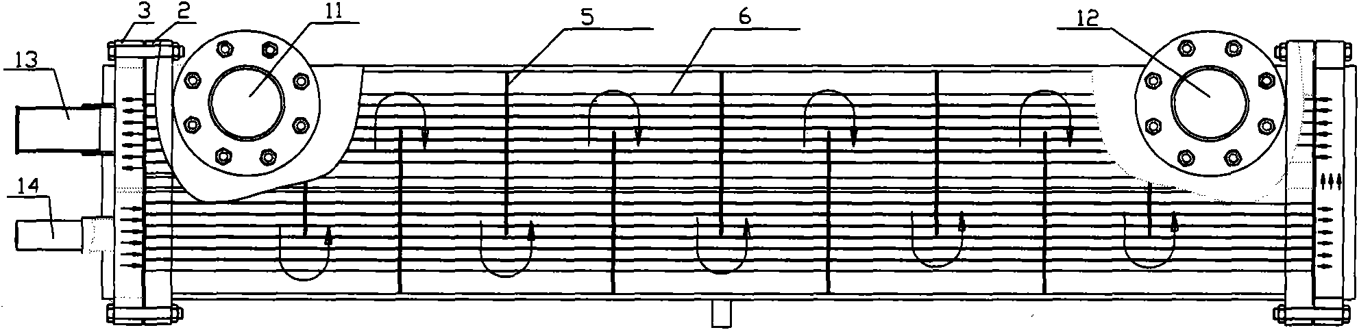
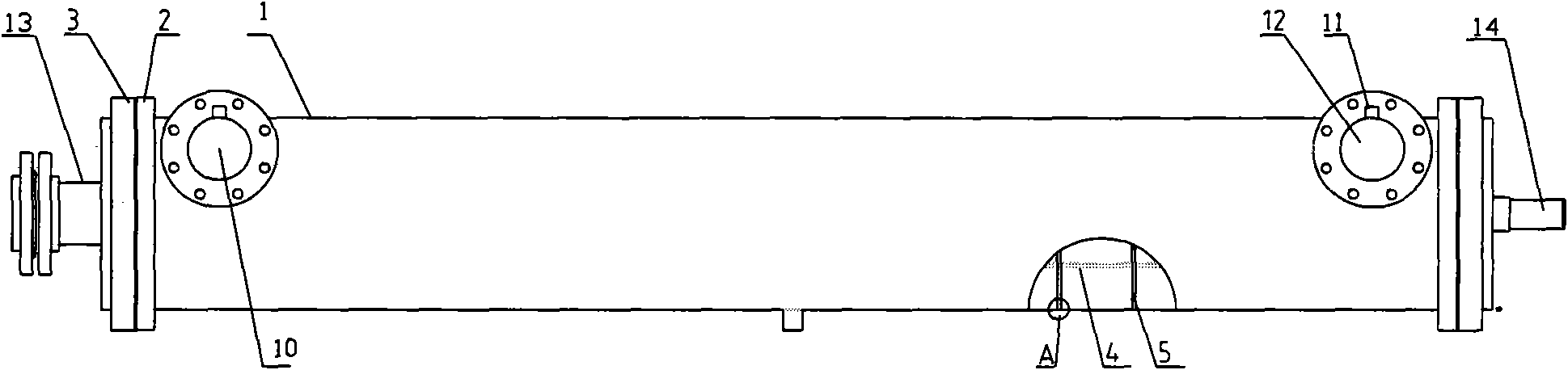
[0022] exist figure 2 Among them, the shell-and-tube heat exchanger includes a tubular shell 1, a tube sheet 2 provided at both ends of the tubular shell 1, and an end cover 3 fixedly connected to the tubular shell 1 along the outer side of the tube sheet 2, A refrigerant inlet 13 is provided on one end cover 3 , and a refrigerant outlet 14 is provided on the other end cover 3 , and a water outlet 10 and a water inlet 12 are correspondingly provided on the outer wall near the tube plate 2 at both ends of the tubular shell 1 , The water outlet 10 and the water inlet 12 are respectively provided with temperature sensing ports 11 .

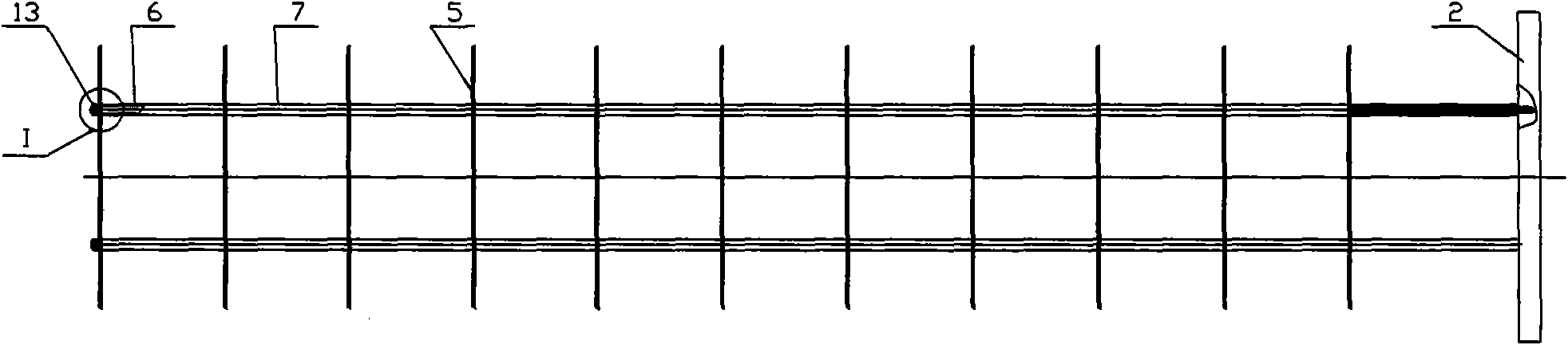
[0023] exist image 3 , 8 In the inner cavity of the shell 1 and between the two tube sheets 2, there are also hollow heat exchange tube bundles 4 and baffles 5, the baffles...


PUM


Abstract

A shell-and-tube heat exchanger comprises a tubular shell, tube sheets arranged along two ends of the tubular shell and an end cover which is fixedly connected to the end of the tubular shell on the outer side of the tube sheets. A cavity of the shell and the tube sheet are provided with a whirl plate, a hollow coil heat exchanger bundle, a pull rod and a pipe spacer. Pores are uniformly arrangedon the whirl plate and periphery of the whirl plate is provided with a soft edge. The hollow coil heat exchanger bundle passes through the pore on the whirl plate and is fixed between two tube sheets.The hollow heat exchanger is the hollow coil heat exchanger bundle, tube wall of which has a continuous spiral slot shape and the external surface of which also has a spiral slot shape. The inventionavoids short circuit and split stream of flow media formed in the shell, and water is forced to spirally flow from a flowing pore gap, which is formed between the pore on the whirl plate and the spiral heat exchanger bundle, through the heat exchanger bundle. The invention improves heat-exchanging efficiency, enables shell side fluid to flow through a reasonable passage, reduces local scour, andeffectively prevents corrosion of the whirl plate, with clean and pollution-free water.

Description

technical field [0001] The invention relates to refrigeration equipment, in particular to a shell-and-tube heat exchanger. Background technique [0002] At present, the shell-and-tube heat exchangers used in central air-conditioning are composed of shells, heat transfer tube bundles, tube sheets, baffles (baffles), and tube boxes. The shell is mostly cylindrical, with a tube bundle inside, and the two ends of the tube bundle are fixed on the tube sheet. There are two kinds of hot and cold fluids for heat exchange, one flows inside the tube, called tube-side fluid; the other flows outside the tube, called shell-side fluid. In order to improve the heat transfer partial coefficient of the fluid outside the tube, several baffles are usually installed in the shell. The baffle not only provides support for the tubes, but also increases the velocity of the shell-side fluid, forcing the fluid to pass through the tube bundle multiple times according to the prescribed path, and enha...

Claims


Application Information

Patent Timeline
Patent Type & Authority Applications(China)
IPC IPC(8): F28D7/10F28F9/24F28F1/34F25B39/02
Inventor 袁博洪唐禄顺罗跃斌
Owner 广州联合冷热设备有限公司
Why Eureka
Try Eureka