Supercharge Your Innovation With Domain-Expert AI Agents!

Radiating module of dry type transformer

A dry-type transformer and heat-dissipating module technology, applied in transformer/inductor cooling, non-varactor pump, machine/engine, etc., can solve the problems of inability to rotate the fan blade, difficult maintenance, and increase the height of the transformer, and achieve Easy adjustment of position and height, enhanced cooling effect, high running balance

Inactive Publication Date: 2011-06-22
苏州工业园区三埃国际科技有限公司
View PDF1 Cites 0 Cited by
  • Summary
  • Abstract
  • Description
  • Claims
  • Application Information

AI Technical Summary

Problems solved by technology

[0008] Ⅳ. Wiring method: The cross-flow fan has a large volume, and is usually fixed with a frame before wiring. At the same time, its terminal row is exposed, and the wiring path is uneven, so it is difficult to tidy up the wiring from the appearance.
If the electrical control unit of the fan needs to be wired by the user, the possibility of wrong connection is often easy to occur
[0009] Ⅴ. Position adjustment: When installed on transformers of different specifications, the cross-flow fan needs special consideration to adjust the relative position between the fan body and the winding, so that the airflow can blow in at the best angle; but when encountering a transformer with a small capacity, the fan When the installation space is insufficient, it is necessary to increase the height of the transformer, resulting in an increase in material costs and a waste of space for the height of the transformer
[0010] VI. Structural firmness: The casing of the cross-flow fan generally has no special load-bearing design. During assembly and use, it is often easily deformed by stepping on it, and sometimes even the fan blade cannot rotate.
[0011] VII. Since the production of cross-flow fans is not common, and the versatility of different specifications is poor, once the fan fails, it is not easy to replace the product of the same specification immediately, and it is difficult to maintain
[0012] Based on the above description of the structural characteristics of the cross-flow fan and the defects in the seven aspects of its application, it can be seen that the cross-flow cooling fan is generally used as the heat dissipation device of the dry-type transformer in the prior art, and there are many inconveniences and hidden dangers to safe operation.

Method used


Image

  • Radiating module of dry type transformer
  • Radiating module of dry type transformer
  • Radiating module of dry type transformer

Examples


Embodiment 1

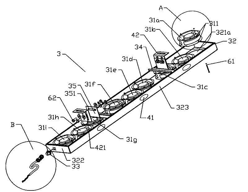
[0041] like Figure 3 to Figure 5 The structural schematic diagram of the inner bottom side of a preferred embodiment of the heat dissipation module of the present invention and the enlarged schematic diagrams of parts A and B are combined as follows Figure 8As shown in the schematic diagram of its structural appearance, it can be understood that the heat dissipation module 3 for cooling dry-type transformers mainly includes a rectangular frame 32 with an open bottom, and three sets of shafts assembled in the frame 32. Flow fan unit (in this embodiment, there are 9 axial flow fans in total, and every 3 fans form a group). The power terminals of all these axial flow fans 31a-31i are collected and connected in parallel to the bus interface 33 provided on one side 322 in the height and width direction of the rack. And the top surface 321 of this frame 32 (as Figure 8 (shown) corresponds to the air outlet of the installed axial flow fan 31a, and the air outlet 321a is carved o...

Embodiment 2

[0048] like Image 6 Shown is a schematic view of the structural appearance of a preferred embodiment of the present invention. The structural features and assembly features of the heat dissipation module in this embodiment are basically the same as those in the first embodiment, so the same parts will not be described again. The difference is that each group of axial-flow fan units contains only one fan, and the motor axes of each fan are located on the same straight line in the length direction, that is, the axis distribution trace α is formed.

Embodiment 3

[0050] like Figure 7 Shown is a schematic view of the structural appearance of another preferred embodiment of the present invention. The structural features and assembly features of the heat dissipation module of this embodiment are basically the same as those of the previous two embodiments, so the same parts will not be repeated here. The difference is that each group of axial-flow fan units contains only two fans, and the motor axes of each fan are located on the same straight line in the length direction, that is, the axis distribution trace α is formed.

[0051] In addition to the above-mentioned embodiments, the present invention can also improve the wiring method to pursue more convenient maintenance and more beautiful effects. The specific method is: on the inner side of the top surface 321 of the frame 32, a plurality of conducting lines (not shown) are closely arranged, and one end of each conducting line is connected to the bus interface 33, and the other end is ...


PUM


Abstract

The invention discloses a radiating module of a dry type transformer. Axial fans are used for replacing original cross-flow cooling fans. The radiating module is characterized by comprising a rectangular stand and three sets of axial fans which are arranged in the stand, wherein the motor axle center of each fan is parallel to the coil axle center of the transformer; the power wire connection endof each fan is connected to a bus interface in parallel, and the bus interface is arranged on a side face of the stand in the height and width direction; ventilation holes which correspond to air outlets of each axial fan is arranged on the top surface of the stand in a hollow mode; and the side of the stand in the height and width direction is provided with a first connecting part used for fixedly connecting the stand to a supporting table of the transformer. After the design scheme of the invention is put into use, the cooling effect of the radiating module to the dry type transformer can be improved, and meanwhile, the invention has the advantages of high fan operation balance, low noise, high operation reliability of the radiating module, convenient wire connection, easy position and height adjustment, firm and beautiful structure, easy maintenance and quick recovery and use.

Description

technical field [0001] The invention relates to a heat dissipation module, in particular to a heat dissipation module of a dry-type transformer, which is used for cooling the coil winding of the dry-type transformer. Background technique [0002] Dry-type transformers generate a lot of heat during normal operation, which needs to be dissipated as soon as possible. At present, the heat dissipation of this kind of transformer is air-cooled, that is, the fan is used to blow air to achieve the purpose of heat dissipation. Most of the existing dry-type transformer heat dissipation fans use ordinary induced draft fans and a volute-shaped fan casing, the side of which is an axial air inlet, and the tangential direction of the casing has an exhaust outlet, and a plate is installed inside the casing. Shaped blades are connected to the motor shaft, and the blade bearings are supported on the housing. This kind of heat dissipation fan is very noisy, vibrates violently during operation,...

Claims


Application Information

Patent Timeline
Patent Type & Authority Patents(China)
IPC IPC(8): H01F27/08F04D29/54
Inventor 刘仲豪
Owner 苏州工业园区三埃国际科技有限公司
Features
  • R&D
  • Intellectual Property
  • Life Sciences
  • Materials
  • Tech Scout
  • Unparalleled Data Quality
  • Higher Quality Content
  • 60% Fewer Hallucinations
Learn More