High-tightness flow battery

A high-level flow battery technology, applied in secondary batteries, regenerative fuel cells, circuits, etc., can solve problems such as large contact resistance of flow batteries, reduce battery internal resistance, improve battery voltage efficiency, and increase battery energy. The effect of efficiency

Inactive Publication Date: 2010-02-17
CENT SOUTH UNIV +1
View PDF1 Cites 31 Cited by
  • Summary
  • Abstract
  • Description
  • Claims
  • Application Information

AI Technical Summary

Problems solved by technology

[0004] The present invention provides an improved assembly method to overcome the problem of relatively large contact resistance of the flow battery in the prior art

Method used


Image

  • High-tightness flow battery
  • High-tightness flow battery
  • High-tightness flow battery

Examples


Embodiment

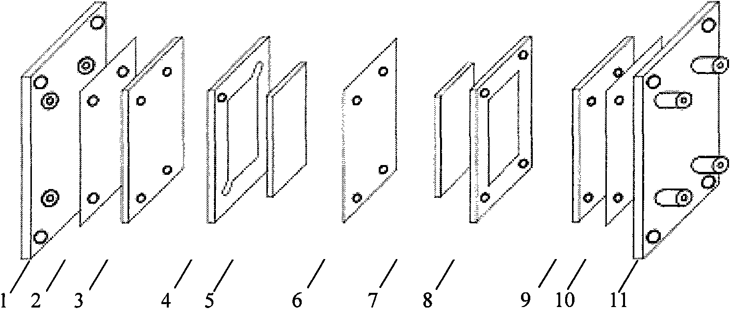
[0019] Description of parts used:

[0020] End plate: PVC material, 3cm thick

[0021] Current collector (single collector plate): isostatic high-density graphite plate, thickness 6mm

[0022] Positive electrode: polyacrylonitrile-based graphite felt, thickness 5mm, produced by Hunan Jiuhua Carbon Co., Ltd.

[0023] Negative electrode: Polyacrylonitrile-based graphite felt with a thickness of 5mm, Hunan Jiuhua Carbon Co., Ltd.

[0024] Liquid flow frame: sheet polyurethane, thickness 5mm

[0025] Proton exchange membrane (diaphragm): homogeneous cation exchange membrane (domestic PE-01), thickness 0.3mm

[0026] Conductive adhesive: ZY518 graphite filled conductive adhesive, produced by Zhuoyi Chemical

[0027] Adhesive: epoxy resin E-44, polyamide resin 650#

example 1

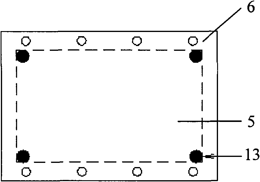
[0029] The flow frames 4, 8 and the membrane 6 of the flow battery are bonded side by side and in parallel with the adhesive, the outer edge of the membrane 6 overlaps with the edge of the outer frame of the flow frame, and the bonding part of the adhesive is the outer edge of the membrane and the liquid flow frame. The outer edge of the outer frame of the flow frame; the shape and size of the electrodes 5 and 7 are the same as those of the inner frame of the flow frame 4 and 8, the electrodes 5 and 7 are embedded in the flow frame, and the membrane 6 and the electrodes 5 and 7 pass through Conductive adhesives are bonded side by side in parallel to form an integrated structure.

[0030] The liquid flow frames 4, 8 and the film 6 are bonded with epoxy resin, and the electrodes 5, 7 and the film 6 are bonded with graphite-filled conductive adhesive. In this device, the outer frame of the liquid flow frame is 80mm×70mm, the inner frame is 40mm×40mm, and the thickness of the liqu...

example 2

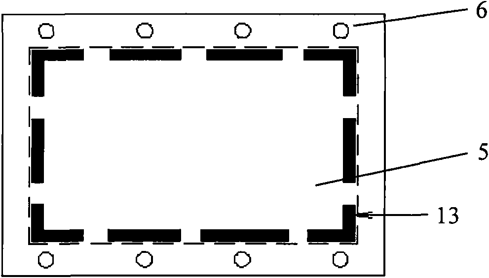
[0032] In this embodiment, epoxy resin and polyamide resin are used for the bonding of liquid flow frames 4, 8 and membrane 6 in a volume ratio of 1:0.1 to 10 and are evenly mixed as an adhesive for bonding. Graphite-filled conductive adhesives are used for bonding. In this device, a homogeneous positive membrane is used with a thickness of 0.3mm. The outer frame of the flow frame is 370mm×270mm, the inner frame is 320mm×210mm, and the thickness of the flow frame is 5mm; the effective area of ​​the electrode is 320mm×210mm. The thickness is 5mm, and the electrode and the film are bonded with conductive glue. The conductive glue is coated on the film with four sides 13 (the way of combining dots and lines), close to the outer edge of the electrode, and the dotted line indicates the outer edge of the electrode (See image 3 ).


PUM

PropertyMeasurementUnit
thicknessaaaaaaaaaa

Abstract

The invention provides a flow battery integrating device which comprises a negative electrode flow frame, a negative electrode, a proton exchange membrane, a positive electrode and a positive electrode flow frame which are sequentially connected with each other. The proton exchange membrane and the flow frames are spliced by acid-resistant binding agent, and the positive electrode and the proton exchange membrane, and the negative electrode and the proton exchange membrane are splice by conductive adhesive. Because the proton exchange membrane, and the flow frames and the electrodes on both sides are integrated in a bonding method, the invention simplifies the battery assembling process and enhances the tightness of the battery, and meanwhile, the integrating device reduces contact resistance between the membrane and the electrodes due to the integration of the membrane and the electrodes so as to reduce the internal resistance of the battery and enhance the efficiency of the battery.

Description

technical field [0001] The invention relates to the field of flow batteries, and more specifically designs the assembly method of the flow batteries. Background technique [0002] The battery stack of a flow battery (such as a vanadium redox flow battery) is usually composed of a certain number of single cells connected in series. Each single cell is composed of a current collector (single collector plate), a liquid flow frame, an electrode, a diaphragm, an electrode, a liquid flow frame, and a current collector (single collector plate). Taking a battery stack composed of two single cells as an example, starting from the liquid inlet according to the end plate, current collector (single collector plate), liquid flow frame, electrode, diaphragm, electrode, liquid flow frame, current collector ( Vanadium battery is assembled in the order of liquid flow frame, electrode, collector plate (single collector plate), and end plate. The installation diagram of the battery stack is ...

Claims


Application Information

Patent Timeline
Patent Type & Authority Applications(China)
IPC IPC(8): H01M8/18H01M10/36
CPCY02E60/12Y02E60/528Y02E60/10Y02E60/50
Inventor 刘素琴陈若媛黄可龙张庆华史小虎仲晓玲李虹云刘维维吴雪文刘根深
Owner CENT SOUTH UNIV
Why Eureka
Try Eureka