Wire saw and method for producing a wire saw

A technology of wire saw and wire frame, which is applied in the field of dividing multiple ceramic components from ceramic component blocks to achieve the effects of small load, small friction and simple cost

Inactive Publication Date: 2010-02-17
SIEMENS AG
View PDF1 Cites 5 Cited by
  • Summary
  • Abstract
  • Description
  • Claims
  • Application Information

AI Technical Summary

Problems solved by technology

This distance of a few millimeters is of course too small for the required cutting width of piezo stacks or piezo stacks, so the wire saws known from semiconductor technology cannot be used for separating ceramic components such as piezo stacks.

Method used


Image

  • Wire saw and method for producing a wire saw
  • Wire saw and method for producing a wire saw
  • Wire saw and method for producing a wire saw

Examples


Embodiment Construction

[0041] In all figures, unless otherwise stated, identical or functionally identical elements and devices are identified with the same reference symbols.

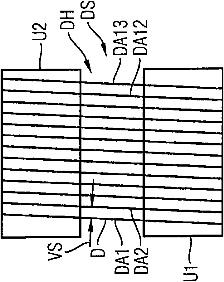
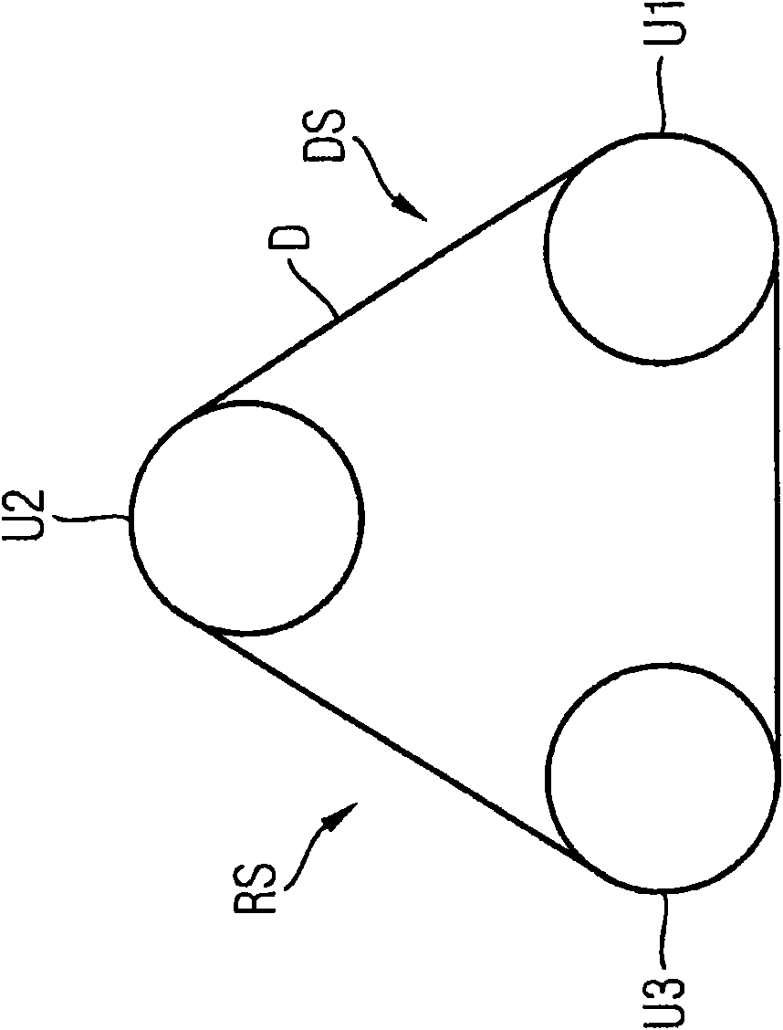
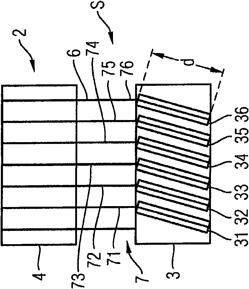
[0042] Figure 2A with 2B A schematic longitudinal section and a schematic transverse section of an exemplary embodiment of a wire saw S according to the invention are shown. pass image 3 This embodiment of the wire saw DS is further illustrated, showing a press Figure 2A A schematic longitudinal sectional view of , with a schematically shown ceramic component block 1 . The wire saw S is suitable for separating a plurality of ceramic components 11 - 16 from the ceramic component block 1 . For this purpose, the wire saw S has a roller system 2 with a plurality of deflection rollers 3 - 5 . exist Figure 2A , 2B Two or three conversion rolls 3-5 are shown in and 3, but not limited thereto. The deflection rollers 3 - 5 guide the wire 6 or the continuous wire so as to form the wire frame 7 . The wire 6 or its coils 61...


PUM

PropertyMeasurementUnit
thicknessaaaaaaaaaa

Abstract

The invention relates to a wire saw (S) for separating a plurality of ceramic components (11-16) from a ceramic component block (1), comprising a roller system (2), said roller system comprising a plurality of deflecting rollers (3-5) guiding a wire (6) to form a wire harp (7), wherein at least one of the deflecting rollers (3) is divided into separate discs (31-36) guiding a single wire winding (61-66) of the wire (6) and being inclined at an adjustable angle (a) of less than 90 DEG to an axle (A) connecting the centers (M1-M6) of the discs (31-36).

Description

technical field [0001] The present invention relates to a wire saw for dividing a plurality of ceramic elements from a ceramic element block, and also relates to a method for dividing a plurality of ceramic elements from a ceramic element block. Background technique [0002] Ceramic elements are, for example, piezoelectric laminates or piezoelectric stacks, which are used in the production of piezoelectric actuators. [0003] Piezoelectric actuators usually consist of multiple piezoceramic discs. Piezoelectric ceramics are materials that elongate when a voltage is applied due to the piezoelectric effect. This piezoceramic forms the basis of piezoelectric actuators, which achieve a travel distance of a few micrometers when an electric voltage is applied. Piezoelectric ceramics have electric dipole moments, which each have a preferential direction in the Weiss field regions, which are separated from each other. In the unpolarized ground state of piezoelectric ceramics, the ...

Claims


Application Information

Patent Timeline
Patent Type & Authority Applications(China)
IPC IPC(8): B23D57/00
CPCB23D57/0061B23D57/0023Y10T29/42Y10T83/9292
Inventor C·哈曼C·舒
Owner SIEMENS AG
Why Eureka
Try Eureka