Field detection control method of tomography foundation pile acoustic transmission method and device thereof

A technology of detection control and transmission method, which is applied in the use of sound waves/ultrasonic waves/infrasonic waves to analyze solids, infrastructure engineering, and foundation structure tests. It can solve problems such as complex on-site operations, hindering applications, and cumbersome operating procedures.

Active Publication Date: 2010-02-24
武汉中岩科技股份有限公司
View PDF2 Cites 22 Cited by
  • Summary
  • Abstract
  • Description
  • Claims
  • Application Information

AI Technical Summary

Problems solved by technology

For each of the J transmitting measuring points at the bottom of the pile and the top of the pile, since they correspond to non-complete detection sector intervals, the number of detection lines constituting each non-complete detection sector interval is not the same, completing an incomplete detection sector After the detection of the interval, the distance of the receiving sensor moving down is also different, and the on-site operation is more complicated
During this kind of on-site operation, the receiving sensor sometimes increases the spacing of one measuring point, and sometimes moves down multiple measuring points, which makes the on-site operation process very cumbersome, error-prone, and detection efficiency is extremely low
At present, there is no efficient on-site detection and control method and device for tomography detection of foundation pile transmission method, which greatly hinders the application of tomography (CT), an accurate and effective detection method, in foundation pile integrity detection. application

Method used


Image

  • Field detection control method of tomography foundation pile acoustic transmission method and device thereof
  • Field detection control method of tomography foundation pile acoustic transmission method and device thereof
  • Field detection control method of tomography foundation pile acoustic transmission method and device thereof

Examples


Embodiment 1

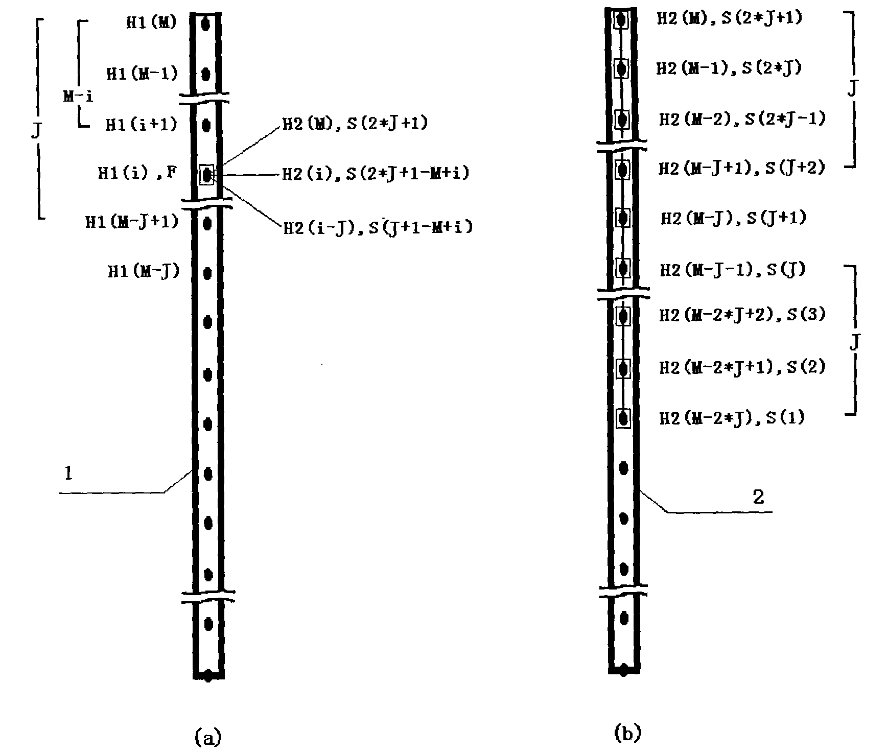
[0102] For a detection profile of a 40-meter-long foundation pile, the span of the detection profile is 1.5 meters, the distance between measuring points is 0.1 meters, and one transmitting measuring point corresponds to 9 (N=2*J+1=9, J=4) receiving measuring points. point, that is, each detection sector corresponds to 9 receiving measurement points. Use has 9 detecting parts S (1), ..., S (9), and the interval of detecting parts is the strobe acoustic wave receiving sensor S of 0.1 meter, (also can use to have more detecting parts Gate the acoustic wave receiving sensor S, but only use the first 9 detection components S(1), ..., S(9)) in the detection, and gate the 9 detection components S of the acoustic wave receiving sensor S (1), ..., S (9) are arranged from bottom to top. The emission measurement points are arranged at a distance of 0.1 meters in the acoustic emission measurement tube, and there are a total of M=401 emission measurement points, where H1(1)=40.0 meters, ...

Embodiment 2

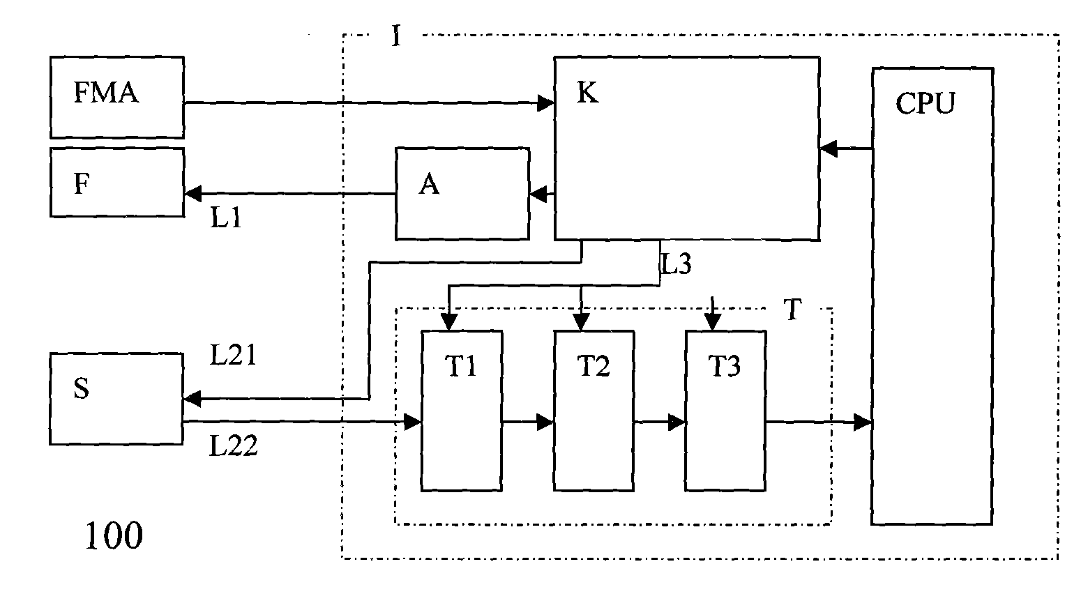
[0142] see figure 1 , which shows a structural block diagram of a detection and control device 100 for foundation pile acoustic wave transmission method according to an embodiment of the present invention. Such as figure 1 As shown, the detection and control device 100 of the sound wave transduction foundation pile sound wave transmission method is composed of a sound wave instrument I, a depth position encoder FMA, a sound wave emission sensor F, and a strobe sound wave reception sensor S. The depth position encoder FMA, the sound wave emission sensor F, The strobe acoustic wave receiving sensors S are all connected with the acoustic wave instrument I through corresponding interfaces. The acoustic wave instrument I is further composed of a computer system CPU, a control unit K, an acoustic wave transmitter A, and an adjustable acoustic wave receiving channel T, wherein the control unit K and the adjustable acoustic wave receiving channel T are connected to the computer sys...

Embodiment 3

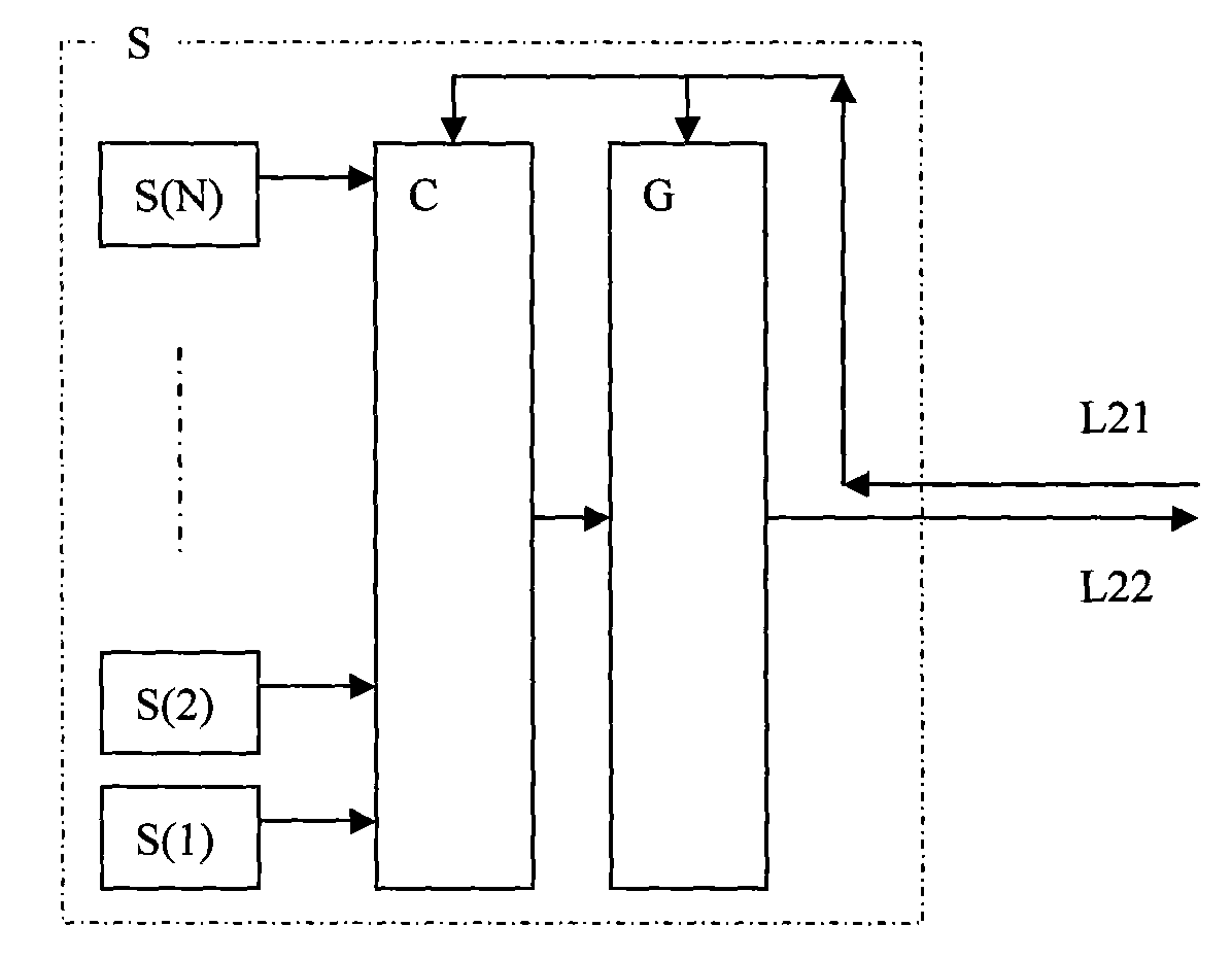
[0165] see figure 1 , figure 2 , image 3 , Figure 4 , Figure 5 , Figure 6 , Figure 7 , Figure 9 , Figure 10 , according to another embodiment of the present invention, the depth position encoder FMA ( figure 1 shown), acoustic emission sensor F ( figure 1 shown), the strobe acoustic wave receiving sensor S ( figure 1 , figure 2 shown), the gating part C of the gating acoustic wave receiving sensor S ( Figure 6 shown), computer system CPU ( figure 1 shown), control unit K ( figure 1 shown), acoustic transmitter A ( figure 1 Shown), sound wave reception can be set to filter circuit T1 of channel T ( Figure 7 shown), the A / D conversion circuit T3 of the acoustic wave receiving channel T can be set ( Figure 9 Shown) are all identical with embodiment 2, do not repeat description here. The only difference from Embodiment 2 is the amplifying circuit T2 of the acoustic wave receiving channel T, and only another embodiment thereof will be described her...


PUM


Abstract

The present invention discloses a field detection control method of tomography foundation pile acoustic transmission method and device thereof, wherein the method comprises includes the following step: A. placing an acoustic emission sensor to the bottom of emission acoustic pipe and placing a gating acoustic receiving sensor to the bottom of receiving acoustic pipe; B. setting a control unit by the computer system CPU; C. detecting the nonholonomic detecting sector sections with the number of pile bases by the control unit; D. detecting M-2*J detecting sector sections at the middle segment ofthe pile body by the control unit K; and E. detecting J nonholonomic detecting sector sections by the control unit K. A depth position coder, an acoustic wave transmission sensor and the gating acoustic receiving sensor are connected with a sonic apparatus. The gating acoustic receiving sensor is composed of a gating component, a settable amplifying component, N detecting components, a control line L21 and a signal line L22. The method of the invention has the advantages of simple operation and simple structure and is suitable for the field detection for executing the acoustic transmission method for detecting the integrity of the foundation pile based on tomography.

Description

technical field [0001] The invention belongs to the technical field of detecting the integrity of foundation piles by using the acoustic wave transmission method based on tomography (CT) technology in the field of geotechnical engineering detection, and specifically relates to a method for on-site detection and control of tomographic imaging pile acoustic transmission method, At the same time, it also relates to a device for on-site detection and control of tomography foundation pile sound wave transmission method. Background technique [0002] Acoustic transmission method to detect the integrity of foundation piles: [0003] To apply the sound wave transmission method in geotechnical engineering to detect the integrity of the poured foundation pile, before pouring concrete, a number of parallel acoustic measuring tubes should be placed on the reinforcement cage of the foundation pile in advance, and the length of the acoustic measuring tube is the same as the length of the ...

Claims


Application Information

Patent Timeline
Patent Type & Authority Applications(China)
IPC IPC(8): E02D33/00G01N29/04
Inventor 张杰胡纯军
Owner 武汉中岩科技股份有限公司
Why Eureka
Try Eureka