Motor control system

A technology for a control device and a motor, which is applied in the directions of motor control, electric controller, program control, etc., can solve the problems of increasing the burden of the computing device and the large amount of calculation, and achieve the effect of realizing model tracking control and reducing the burden.

Active Publication Date: 2010-02-24
SANYO DENKI CO LTD
View PDF5 Cites 5 Cited by
  • Summary
  • Abstract
  • Description
  • Claims
  • Application Information

AI Technical Summary

Problems solved by technology

[0007] However, the calculations used in the conventional technology shown in Patent Document 2 have a problem that the amount of calculations is large and the burden on the calculation device increases.

Method used


Image

  • Motor control system
  • Motor control system
  • Motor control system

Examples


Embodiment Construction

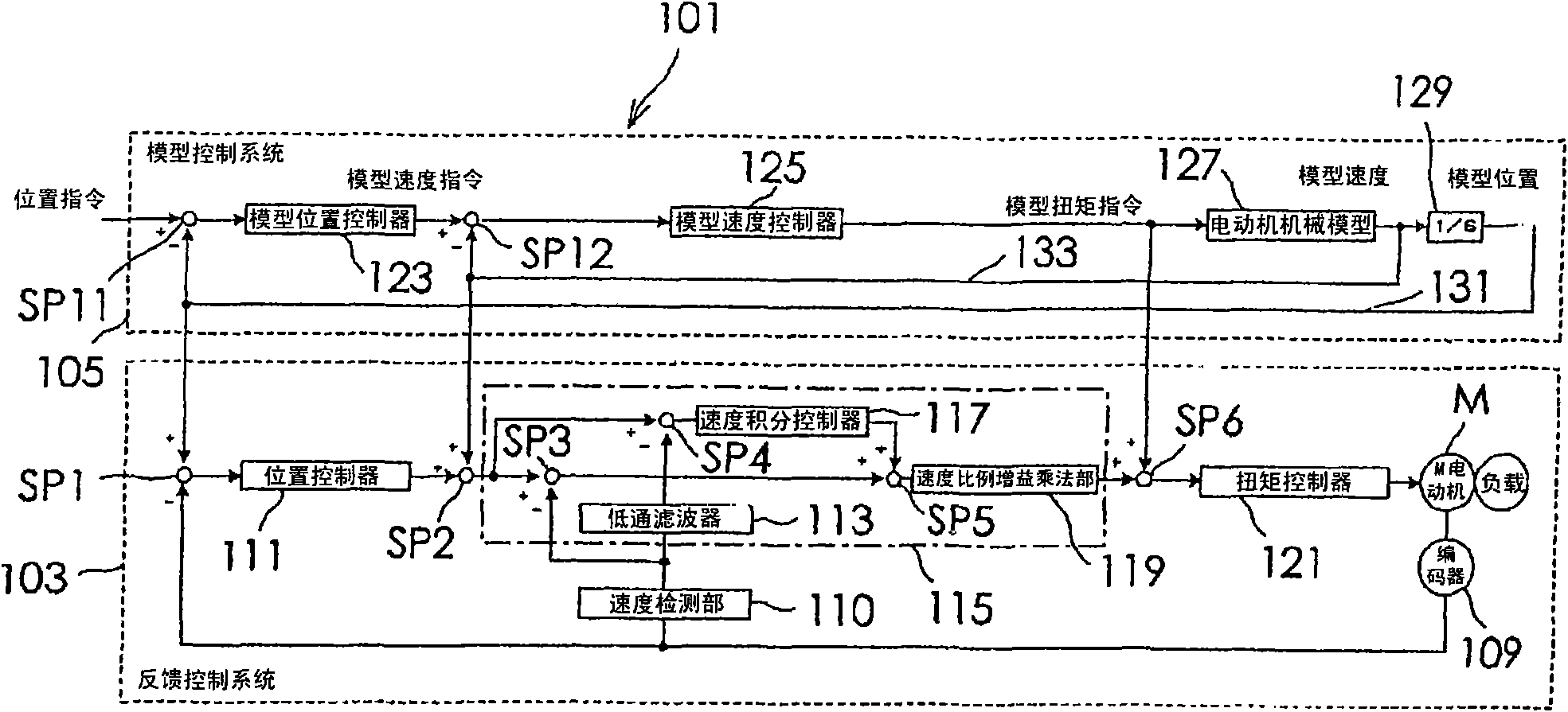
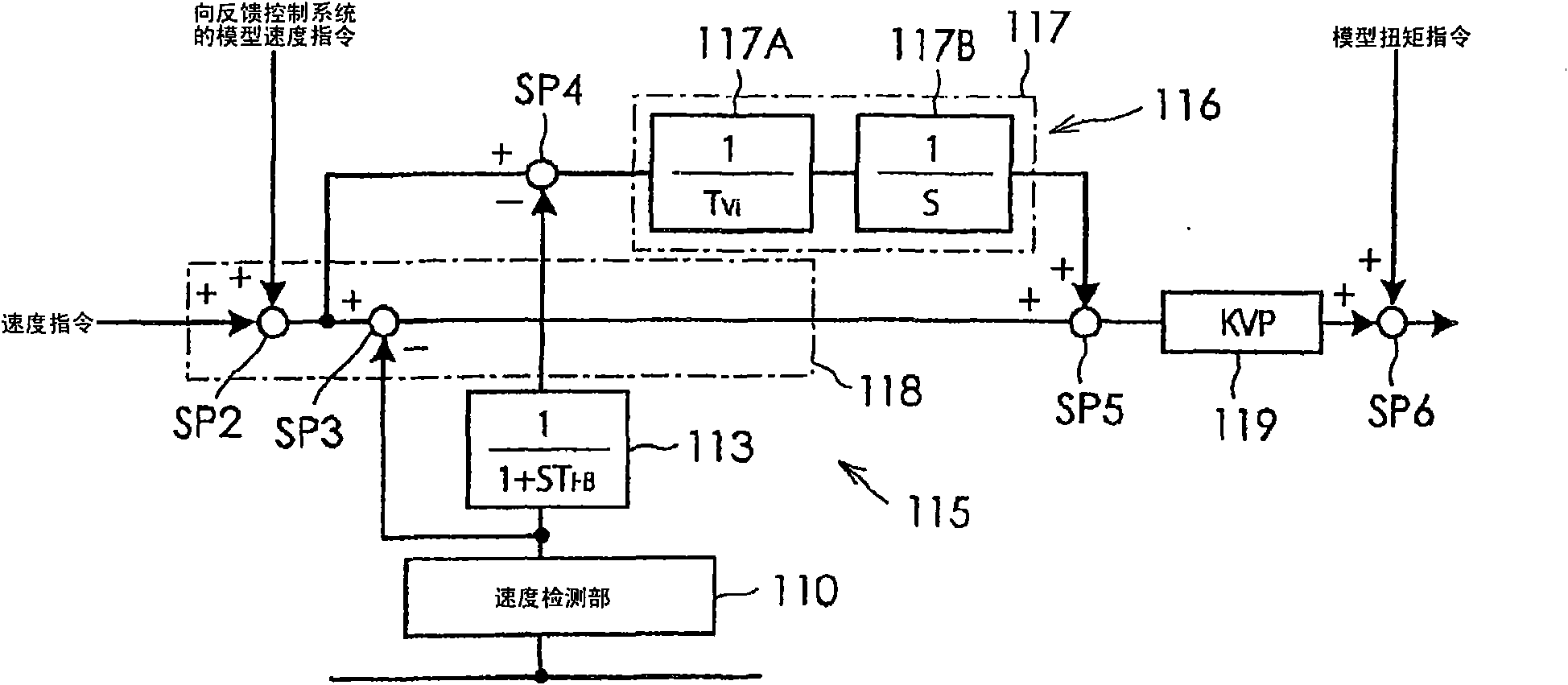
[0023] Hereinafter, embodiments of the present invention will be described in detail with reference to the drawings. figure 1 It is a block diagram showing the configuration of the motor control device of the present invention. figure 2 It is a schematic diagram showing the specific configuration of main parts of the feedback control system 103 . The motor control device 101 of this embodiment is composed of a feedback control system 103 and a model control system 105 . The feedback control system 103 includes: a position sensor 109 composed of an encoder that detects the rotational position of the motor M; a position controller 111 ; a speed detector 110 ; a speed controller 115 ; and a torque controller 121 . The output (position information) of the position sensor 109 is fed back to the position controller 111, and the output (position information) of the position sensor 109 is differentiated by the speed detection unit 110 to be filtered by the low-pass filter 113 as sp...


PUM


Abstract

A motor control system is provided that can execute model following control in which an influence of the difference between the sampling rate of a feedback control system and the sampling rate of a model control system is suppressed with a smaller amount of computation than ever. A speed controller includes a low-pass filter having a transfer function corresponding to the delay in the sampling rate of a model control system, an integral control system including a speed integrator, a proportional control system, and a speed proportional gain multiplication section. The integral control system inputs to the speed integrator a command obtained by a subtraction section that subtracts delay speed information output from the low-pass filter from a command obtained by an addition section that adds a speed command and a model speed command.

Description

technical field [0001] The present invention relates to a motor control device having a model control system for model following control. Background technique [0002] When a machine such as a chip mounter is driven to determine the position at high speed, there is a model following control method as one of methods for determining the position of the machine at high speed by a motor control device. In model following control, a model control system simulating an actual feedback control system is constructed. Also, the feedback control system is driven in such a way as to track the model control system. Figure 6 This shows the configuration of a motor control device using the conventional model-following control method disclosed in JP-A-62-217304 [Patent Document 1]. In this control device, the deviation between the position command and the model position is obtained, and the model speed command is obtained by the model position controller. Then the deviation between the m...

Claims


Application Information

Patent Timeline
Patent Type & Authority Applications(China)
IPC IPC(8): H02P23/14H02P29/00G05B13/04G05D3/12
CPCG05B19/318G05B2219/42011G05B17/02G05B21/02G05B2219/42062G05B11/42G05B2219/42155
Inventor 井出勇治
Owner SANYO DENKI CO LTD
Why Eureka
Try Eureka