Thin-wall annular gear processing method

A processing method and the technology of the inner ring gear are applied in the direction of metal processing equipment, metal processing machinery parts, gear teeth, etc., which can solve the problems of broken teeth, large deformation of the inner ring gear, high cost, etc., and achieve small deformation, high precision, high efficiency effect

Inactive Publication Date: 2010-03-03
CHONGQING QINGPING MACHINERY
View PDF0 Cites 39 Cited by
  • Summary
  • Abstract
  • Description
  • Claims
  • Application Information

AI Technical Summary

Problems solved by technology

[0002] The ratio of the wall thickness to the diameter of the inner ring gear is 1/50, the diameter is also as large as 570mm, and the width is 110mm. Therefore, the deformation of the inner ring gear is very large during the lathing and gear shaping process of the inner ring gear. Generally, the processing deformation is 0.2 ~0.3mm is normal. Many professional manufacturers feel that it is not guaranteed to use a horizontal car, and must use a vertical car. The mechanical performance requirements are high, and

Method used


Image

  • Thin-wall annular gear processing method
  • Thin-wall annular gear processing method
  • Thin-wall annular gear processing method

Examples


Embodiment 1

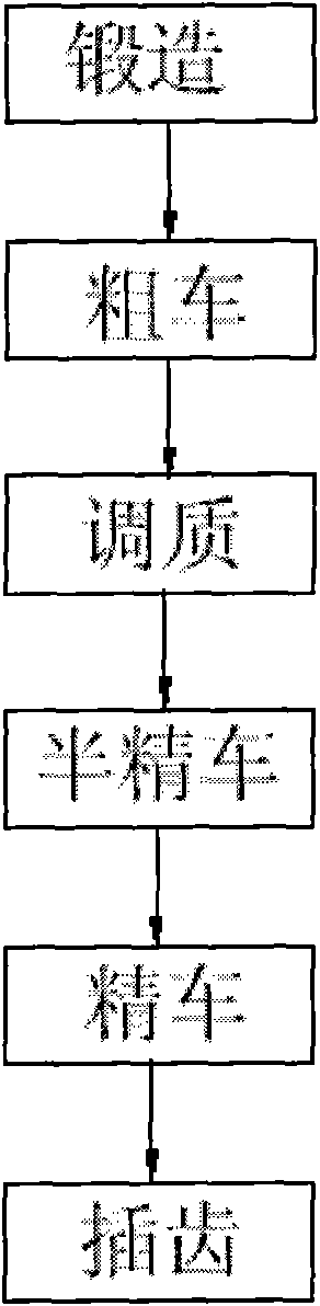
[0015] Example 1: see Figure 1 ~ Figure 3 : The processing method of the thin-walled inner ring gear shown includes the following steps: (1) forging, (2) rough turning, (3) quenching and tempering, (4) semi-finishing turning, (5) finishing turning and (6) inserting teeth, of which:

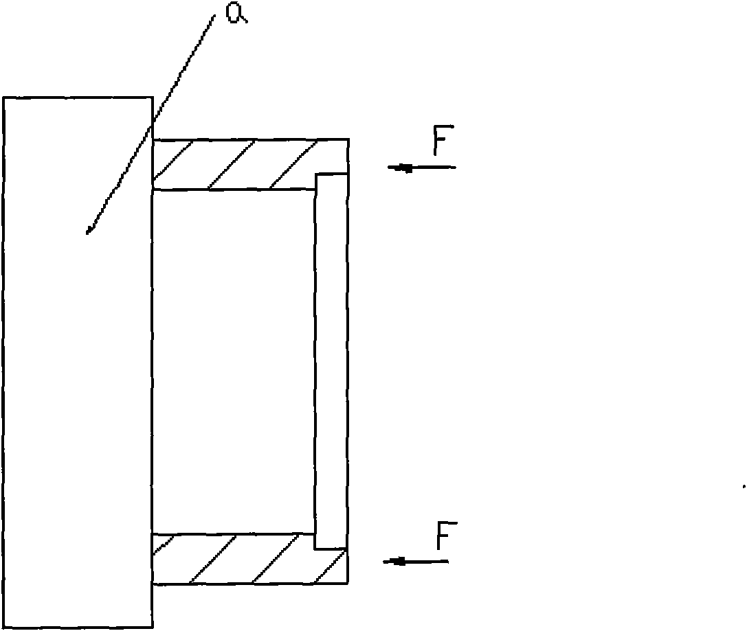
[0016] The step (5) finish turning is: take the end face of the thin-walled inner ring gear after the semi-finishing step (4) as the force-bearing surface, and act axial force to fix the thin-wall inner ring gear on the horizontal lathe for working On platform a, then the inner wall and outer wall of the thin-walled ring gear are turned;

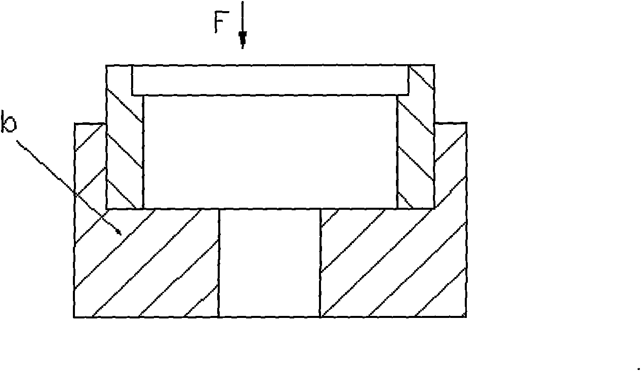
[0017] The step (6) of gear shaping is: using a fixture to simultaneously position the end face and outer wall of the thin-walled inner ring gear after finishing turning in step (5), and then perform gear shaping on the inner wall of the thin-walled inner ring gear.

[0018] In the step (5) in the finish turning process, the bottom surface and the outer circl...

Embodiment 2

[0019] Example 2: see Figure 1 ~ Figure 3 : The processing method of the thin-walled inner ring gear shown includes the following steps: (1) forging, (2) rough turning, (3) quenching and tempering, (4) semi-finishing turning, (5) finishing turning and (6) inserting teeth, of which:

[0020] The step (5) finish turning is: take the end face of the thin-walled inner ring gear after the semi-finishing step (4) as the force-bearing surface, and act axial force to fix the thin-wall inner ring gear on the horizontal lathe for working On platform a, then the inner wall and outer wall of the thin-walled ring gear are turned;

[0021] The step (6) of gear shaping is: using a fixture to simultaneously position the end face and outer wall of the thin-walled inner ring gear after finishing turning in step (5), and then perform gear shaping on the inner wall of the thin-walled inner ring gear.

[0022] See Figure 4 : the clamp adopted in the step (6) gear shaping process is a ring cla...


PUM


Abstract

The invention discloses a thin-wall annular gear processing method which comprises the steps of forging, rough turning, tempering, half finished turning, finish turning and gear shaping, wherein the finish turning process comprises the steps of: taking the end surface of the thin-wall annular gear after half finished turning as a thrust surface, acting the axial force to fix the thin-wall annulargear on a horizontal lathe work bench, and then turning the inner wall and the outer wall of the thin-wall annular gear; and the gear shaping process comprises the steps of: using a fixture to simlutaneously fix the end surface and the outer wall of the thin-wall annular gear after finish turning, and then conducting gear shaping to the inner wall of the thin-wall annular gear. The thin-wall annular gear processing method can lead the thin-wall annular gear after processing to have small deformation, has high precision and high efficiency.

Description

technical field [0001] The invention relates to the technical field of gears, in particular to a processing method for a thin-walled inner ring gear. Background technique [0002] The ratio of the wall thickness to the diameter of the inner ring gear is 1 / 50, the diameter is also as large as 570mm, and the width is 110mm. Therefore, the deformation of the inner ring gear is very large during the lathing and gear shaping process of the inner ring gear. Generally, the processing deformation is 0.2 ~0.3mm is normal. Many professional manufacturers feel that it is not guaranteed to use a horizontal car, and must use a vertical car. The mechanical performance requirements are high, and the precision of the internal teeth is also high. If deformation occurs, the force on the internal teeth will be uneven, and the teeth will easily be broken, causing heavy lifting objects to fall, causing personnel and property losses, and the consequences are unimaginable. In the gear shaping pro...

Claims


Application Information

Patent Timeline
IPC IPC(8): B23P15/14B23B5/00B23F5/12B23Q3/06B23F23/06
Inventor 高传芳冯春艳
Owner CHONGQING QINGPING MACHINERY
Why Eureka
Try Eureka