
Method for eliminating carbon deposited in exhaust pipe of diesel engine

A diesel engine and exhaust pipe technology, which is applied in the electronic control, exhaust treatment, and exhaust devices of exhaust gas treatment devices, can solve problems affecting the smooth exhaust gas performance of diesel engines, carbon deposition, and inability to increase engine operating temperature. and other problems, to achieve the effect of excellent exhaust maintenance and work performance and effective carbon deposition

Inactive Publication Date: 2010-03-03
陈温乐
View PDF0 Cites 1 Cited by
  • Summary
  • Abstract
  • Description
  • Claims
  • Application Information

AI Technical Summary

Problems solved by technology

[0004] The main purpose of the present invention is to solve the existing diesel engine vehicles with smoke exhaust purifier installed in the exhaust pipe at present. Due to differences in environment and conditions, as well as driver habits, the engine speed cannot be increased, so that the engine operating temperature cannot be increased, so that the carbon deposits on the surface of the filter elements cannot be burned smoothly, and carbon deposits will still occur, which will affect the smooth exhaust and the operation of the diesel engine. performance problems, and provide a method to eliminate carbon deposits in the diesel engine exhaust pipe, in order to maintain the smooth exhaust of the diesel engine and the normal operation of the engine

Method used


Image

  • Method for eliminating carbon deposited in exhaust pipe of diesel engine
  • Method for eliminating carbon deposited in exhaust pipe of diesel engine

Examples


Embodiment Construction

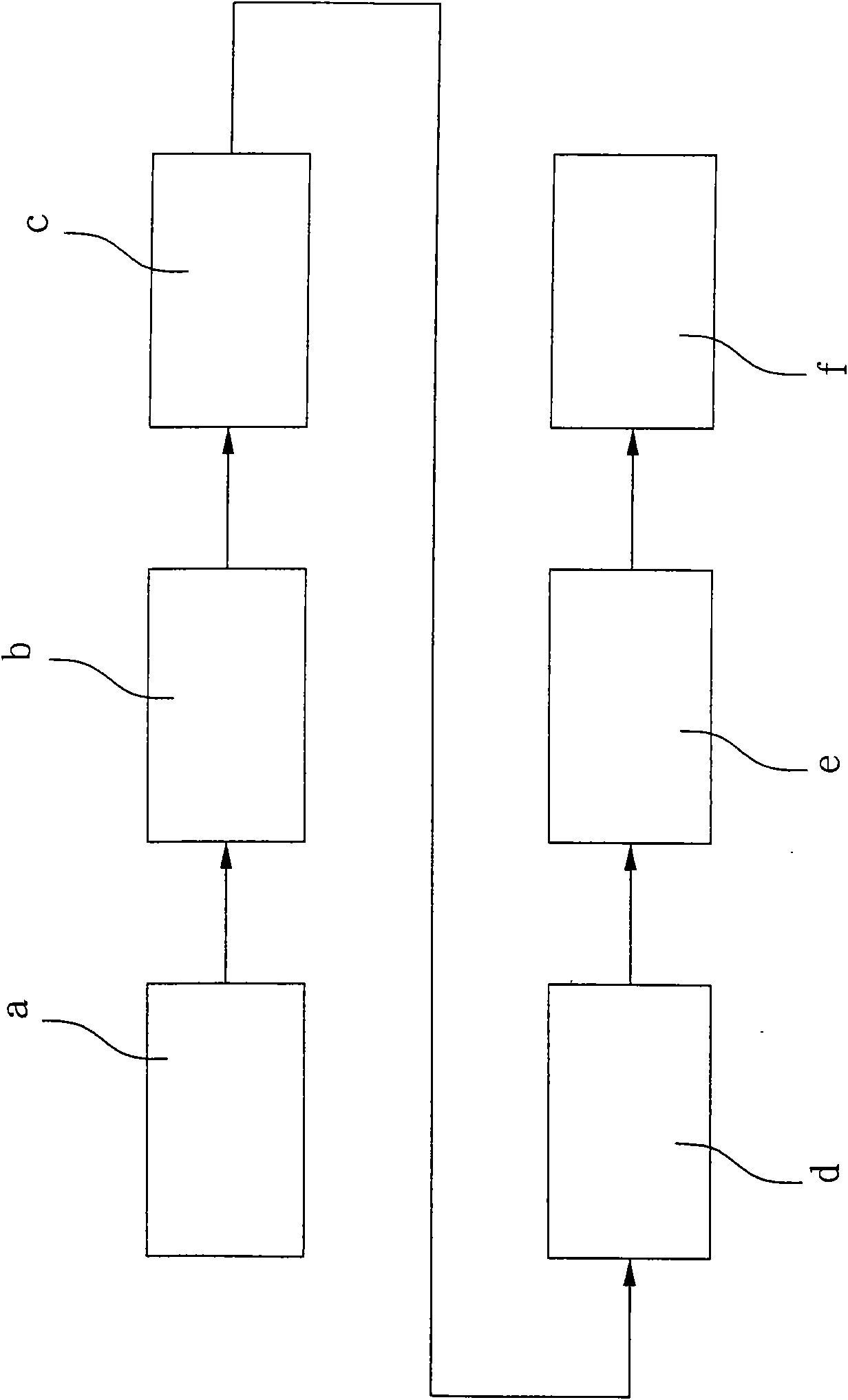
[0039] Such as figure 1 As shown, the method for eliminating carbon deposits in diesel engine exhaust pipes provided by the invention comprises the following steps:

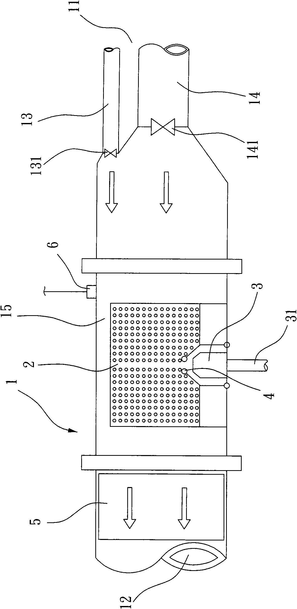
[0040] a. Provide an exhaust pipe, the interior of which is provided with exhaust gas inlet and air inlet, combustion chamber and smoke exhaust purifier in sequence from the direction of air intake to outlet;

[0041] b. detecting the exhaust gas pressure before the exhaust purifier with a sensor;

[0042] c. When the exhaust gas pressure is higher than a preset value, the control system automatically opens the air inlet to guide fresh air into the exhaust pipe and pass through the combustion chamber;

[0043] d. Start a flame spraying device, atomize and inject fuel into the combustion chamber, mix and atomize with air, and ignite and burn to heat to 350°C-600°C;

[0044] e. Let the gas heated to 350°C to 600°C pass through the smoke exhaust purifier to ignite and remove carbon deposits;

[0045] f. When the ...


PUM


Abstract

The invention discloses a method for eliminating carbon deposited in an exhaust pipe of a diesel engine. The method comprises the following steps: providing an exhaust pipe, the inside of which is provided with an exhaust gas inlet, an air inlet, a combustion chamber and a smoke exhaust purifier in sequence from the air inlet end to the air outlet end; detecting the exhaust gas pressure in front of the smoke exhaust purifier by a sensor; automatically opening the air inlet by a control system when the exhaust gas pressure surpasses a pre-set value so as to guide fresh air into the exhaust pipeand pass through the combustion chamber; starting a fire spray device to atomize and spray fuel into the combustion chamber and atomize the fuel together with air while igniting and burning to lift the temperature to between 350 and 600 DEG C; allowing gas heated to a high temperature to pass through the smoke exhaust purifier so as to ignite and remove deposited carbon; and automatically closingthe air inlet and opening the exhaust gas inlet by the control system when the exhaust gas pressure is lower than the pre-set value detected by the sensor so as to guide exhaust gas produced by the diesel engine into the exhaust pipe and discharge the exhaust gas after the exhaust gas passes through the combustion chamber and the smoke exhaust purifier. The method for eliminating carbon depositedin exhaust pipe of diesel engine ensures the smooth gas discharging of the diesel engine and the normal operation of the engine.

Description

technical field [0001] The invention relates to a method for automatically removing carbon deposits in a smoke exhaust purifier installed at the rear end of an exhaust pipe of a diesel engine so as to maintain the diesel engine's smooth discharge of exhaust gas and eliminate carbon deposits in the exhaust pipe of the diesel engine. Background technique [0002] Diesel engines emit a large amount of exhaust gas, seriously pollute the atmosphere, cause the global warming effect and endanger a large number of creatures on the earth. Since the end of the 20th century, it has aroused the concern of people of insight around the world. Especially in the automobile industry, various solutions are continuously proposed. Among them, the smoke exhaust purifier installed at the rear end of the exhaust pipe of the diesel engine is more effective in effectively filtering the exhaust gas emitted by the diesel engine in large quantities. However, after a period of use of this kind of smoke ...

Claims


Application Information

Patent Timeline
Patent Type & Authority Applications(China)
IPC IPC(8): F01N3/20F01N9/00F01N3/28F01N7/08
CPCY02T10/47Y02T10/40
Inventor 陈温乐
Owner 陈温乐
Learn More