Air-conditioning system and control method thereof

An air-conditioning system and controller technology, applied in air-conditioning systems, heating and ventilation control systems, heating and ventilation safety systems, etc., can solve problems affecting comfort, increasing power, increasing hydraulic resistance of pipe networks, etc., to achieve comfortable use Consistent degree, reduce the maximum water pressure, reduce the effect of pipeline resistance

Inactive Publication Date: 2010-03-03
谭仲禧 +1
View PDF0 Cites 11 Cited by
  • Summary
  • Abstract
  • Description
  • Claims
  • Application Information

AI Technical Summary

Problems solved by technology

Since each coil fan unit is scattered in various places in the building, and the distance from the circulating pump is different, the amount of water flowing through the coil fan unit at the far end and the near end is quite different, and the resistance of the system pipe network is also different. It will cause the flow rate of some loops to be too large, the flow rate of some loops to be too small, and the phenomenon of uneven heating and cooling of the system, which seriously affects the comfort. Therefore, the setting of the circulating pump must consider ensuring the remote flow rate and increasing the power, resulting in energy consumption. rise
Although it can be used as Figure 4 The arrangement of pipelines in the same way of return water shown in the figure increases the length of the outlet pipeline of coil fan unit 1, so that the hydraulic resistance at each coil fan unit 1 is basically the same, and the regulating valve 32 makes each coil fan unit The circulating water flow rate is basically close to that of the circulating water, but this arrangement will bring the defect of high pipeline cost. At the same time, the increased pipeline will inevitably increase the hydraulic resistance of the entire pipeline network, and the power of the circulating pump must be further increased to ensure the flow balance. will increase energy consumption

Method used


Image

  • Air-conditioning system and control method thereof
  • Air-conditioning system and control method thereof
  • Air-conditioning system and control method thereof

Examples


Embodiment

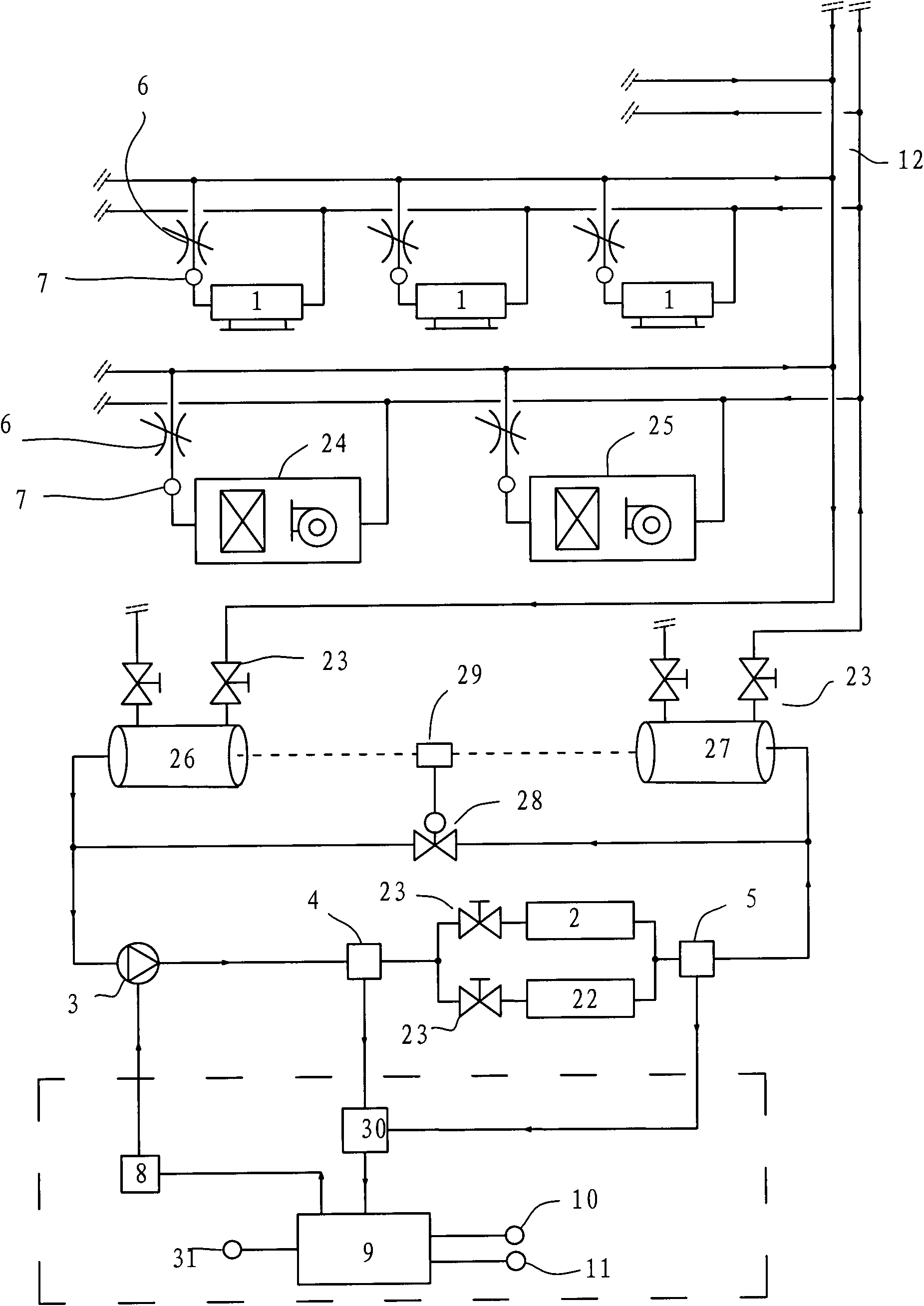
[0020] refer to figure 1 , an air-conditioning system, including a controller 9, a frequency converter 8 connected to the controller 9 for controlling the operating frequency of the circulating pump 3, a circulating pump 3 located on the circulating water circuit 12, and a Chiller unit 2, hot water unit 22, air handling unit 24, fresh air unit 25, and coil fan unit 1 at each user end. The inlet and outlet of the chiller 2 and the hot water unit 22 are respectively provided with an inlet temperature sensor 4 and an outlet temperature sensor 5 that output temperature signals to the controller 9. Since the chiller 2 and the hot water unit 22 are arranged in parallel, the The outlet temperature sensors can share one set; in this embodiment, a temperature difference transmitter 30 connected to the inlet temperature sensor 4 and the outlet temperature sensor 5 is provided, and the temperature difference transmitter 30 is used to output the temperature difference signal of the inlet...


PUM


Abstract

The invention discloses an air-conditioning system and a control method thereof. The air-conditioning system comprises a controller, a frequency converter, a circulating pump, a cold water machine set, a hot water machine set and a coil pipe blower group of each user end, wherein the controller is provided with a frequency-conversion protecting device used for refrigeration; the frequency converter is used for controlling the working frequency of the circulating pump; the circulating pump, the cold water machine set, the hot water machine set and the coil pipe blower group of each user end arepositioned on a circulating water loop, the coil pipe blower groups are respectively connected and arranged on the circulating water loop in parallel, a flow rate automatic balance adjusting valve and a temperature sensor which outputs a temperature signal to the flow rate automatic balance adjusting valve are respectively arranged on the connection pipelines of the coil pipe blower groups, the temperature signal output by the temperature sensor is used for switching the maximum flow rate setting value of the flow rate automatic balance adjusting valve under a refrigeration mode and a heatingmode, the controller controls the constancy of the temperature difference of an inlet and an outlet of the cold water machine set or the hot water machine set by adjusting the working frequency of the circulating pump, and the frequency-conversion protecting device used for refrigeration is switched to a bypass under the heating mode. The invention can correspondingly adjust the frequency of thecirculating pump according to the load change of the system, save energy, lower consumption and control the flow rate in the circulating loop accurately.

Description

technical field [0001] The invention relates to an air-conditioning system and a control method thereof, in particular to a central air-conditioning system. Background technique [0002] In the central air-conditioning system, coil fan units are installed at each end user, chilled water is fed into the coil, and the fan blows cold air into the end user to achieve cooling. The coils in each coil fan unit are respectively connected to the chilled water circulation circuit. The circulation circuit includes a circulation pump and a chiller. Each coil fan unit is arranged in parallel in the circuit, and the circulation pump provides power to make the circulation The water enters the chiller to cool down to form chilled water, which is then transported through pipes to each coil fan unit for use by users. Since each coil fan unit is scattered in various places in the building, and the distance from the circulating pump is different, the amount of water flowing through the coil fa...

Claims


Application Information

Patent Timeline
Patent Type & Authority Applications(China)
IPC IPC(8): F24F3/06F24F11/02F24F11/00
Inventor 谭仲禧梁耀文
Owner 谭仲禧
Why Eureka
Try Eureka