Floating signal contact element and electric connector using the same

A technology of electrical connectors and contacts, which is applied to the device for joining/disconnecting connected parts, two-part connecting device, connection, etc., can solve the problems of large volume, complex matching structure, and difficult manufacture of signal contacts, and achieve the realization of Connected or disconnected, improved anti-vibration, small footprint effect

Active Publication Date: 2010-03-03
CHINA AVIATION OPTICAL-ELECTRICAL TECH CO LTD
View PDF0 Cites 14 Cited by
  • Summary
  • Abstract
  • Description
  • Claims
  • Application Information

AI Technical Summary

Problems solved by technology

[0002] Existing electrical connectors for radio frequency signal transmission generally include a housing and signal contacts installed therein, and the signal contacts include an outer conductor and an inner conductor fixed in the outer conductor through an insulator. The outer conductor of the existing signal contact It is generally fixedly assembled with the housing of the electrical connector. In order to make the signal contact have a certain impact resistance, a spring is installed between the outer conductor and the housing of some signal contacts to achieve relative movement. Due to various Due to the difference in the size of the shell structure of the connector, the matching structure between the existing signal contact and the shell is relatively complicated, it is difficult to assemble and disassemble, and the volume is large, which makes it difficult to manufacture such signal contacts as standard parts and cannot adapt to connection. Requirements for standardization and miniaturization of device design

Method used


Image

  • Floating signal contact element and electric connector using the same
  • Floating signal contact element and electric connector using the same
  • Floating signal contact element and electric connector using the same

Examples


Embodiment Construction

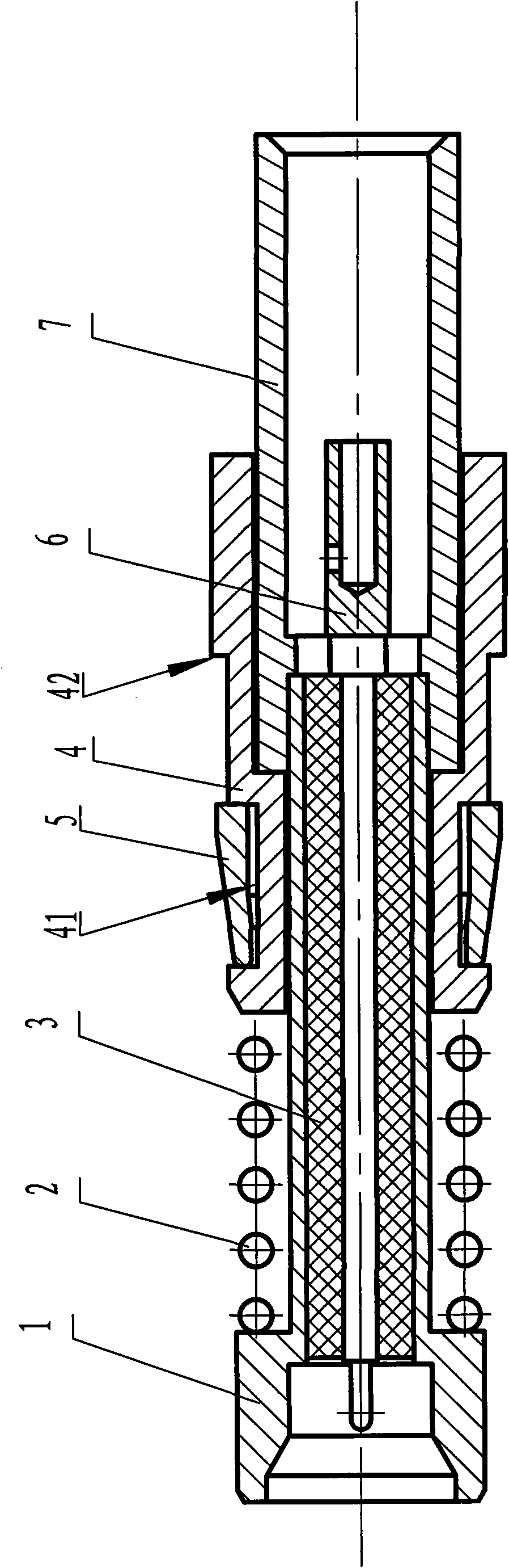
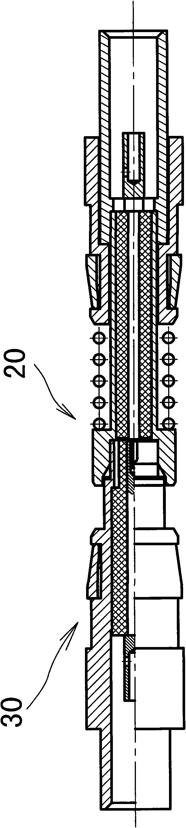
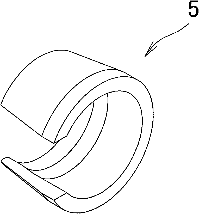
[0021] Such as figure 1 , figure 2 , image 3 As shown, the embodiment of the floating signal contact of the present invention is a high-frequency socket contact, including a floating outer conductor 1 with a through hole inside, and a sleeve-shaped insulator is installed in the through hole inside the floating outer conductor 1 3. The inner conductor 6 is installed in the inner sleeve hole of the insulator 3, and one end of the floating outer conductor 1 is a plug-in end for plugging in with an adapted high-frequency pin contact, and the other end is mated and fixed in a Other radio frequency circuits are connected into the rear sleeve 7, and the front end surface of the rear sleeve 7 forms a second annular step surface on the periphery of the junction of the outer wall of the floating outer conductor 1. The outer wall of the floating outer conductor 1 close to the plug-in end is provided with a ring platform to form a first annular step surface, and the outer wall of the ...


PUM


Abstract

The invention discloses a floating signal contact element and an electric connector using the same. The contact comprises an inner conductor and an outer conductor. A stop collar between a first axiallimit structure and a second axial limit structure on the outer wall of the outer conductor is provided with a spring and a sliding bush glidingly matched with the outer wall of the outer conductor;the sliding bush is assembled between the spring and the second axial limit structure in the mode of axial spacing; the outer wall of the sliding bush is provided with an elastic radial actuating structure and a third axial limit structure which are clamped on the shell of an adaptive connector; the elastic radial actuating structure and the third axial limit structure are relatively arranged, andan intake limit space for the convex part of the shell to enter is formed between the elastic radial actuating structure and the third axial limit structure. The outer conductor of the signal contactelement realizes the detachable assembly between the outer conductor and the shell of the connector through the sliding bush sheathed on the outer conductor and matched with the spring in the mode ofaxial limit, the elastic radial actuating structure on the sliding bush can be clamped on a corresponding structure in the shell of the connector to be in limit match or to be fixed together when being expanded, and can be frapped by a detaching tool to realize separation.

Description

technical field [0001] The invention relates to the technical field of electrical connectors. Background technique [0002] Existing electrical connectors for radio frequency signal transmission generally include a housing and signal contacts installed therein, and the signal contacts include an outer conductor and an inner conductor fixed in the outer conductor through an insulator. The outer conductor of the existing signal contact It is generally fixedly assembled with the housing of the electrical connector. In order to make the signal contact have a certain impact resistance, a spring is installed between the outer conductor and the housing of some signal contacts to achieve relative movement. Due to various Due to the difference in the size of the shell structure of the connector, the matching structure between the existing signal contact and the shell is relatively complicated, it is difficult to assemble and disassemble, and the volume is large, which makes it diffic...

Claims


Application Information

Patent Timeline
Patent Type & Authority Applications(China)
IPC IPC(8): H01R24/02H01R13/73H01R13/62H01R24/40
Inventor 赵纪正王学习
Owner CHINA AVIATION OPTICAL-ELECTRICAL TECH CO LTD
Why Eureka
Try Eureka