X-shaft transmission system for modifying planing machine into milling planer

A technology of gantry milling machine and gantry planer, which is applied in the direction of driving devices, manufacturing tools, metal processing machinery parts, etc. It can solve the problems of large backlash in X-axis transmission, reduce the rigidity of the transmission system, and lower requirements for positioning rigidity. The effect of large clearance, improved machining accuracy, and low material utilization rate

Inactive Publication Date: 2010-03-10
济南迈特力科技集团有限公司
View PDF0 Cites 2 Cited by
  • Summary
  • Abstract
  • Description
  • Claims
  • Application Information

AI Technical Summary

Problems solved by technology

Due to the large backlash of the X-axis transmission, the machine tool cannot be changed into a CNC boring and milling machine
[0004] In addition, after the current gantry planer is changed to a gantry milling machine, due to the heavy weight and long length of the large transmission shaft in the X-axis transmission system, the rigidity of the transmission is reduced. In the form of internal and external gears, the rigidity of the transmission system will be reduced; because the previous planer has an empty stroke in a working cycle, and only one stroke works, the force direction of the table does not change during planing. , so that the positioning rigidity of the X-axis is lower, but after the planer is changed to a milling machine, there is a higher requirement for the position accuracy of the milling machine in the X-axis direction. The current method is to install an X-axis brake device. This method has the shortcomings of time-consuming and labor-intensive modification and poor modification effect

Method used


Image

  • X-shaft transmission system for modifying planing machine into milling planer
  • X-shaft transmission system for modifying planing machine into milling planer
  • X-shaft transmission system for modifying planing machine into milling planer

Examples


Embodiment Construction

[0025] The present invention will be further described below in conjunction with the accompanying drawings and embodiments.

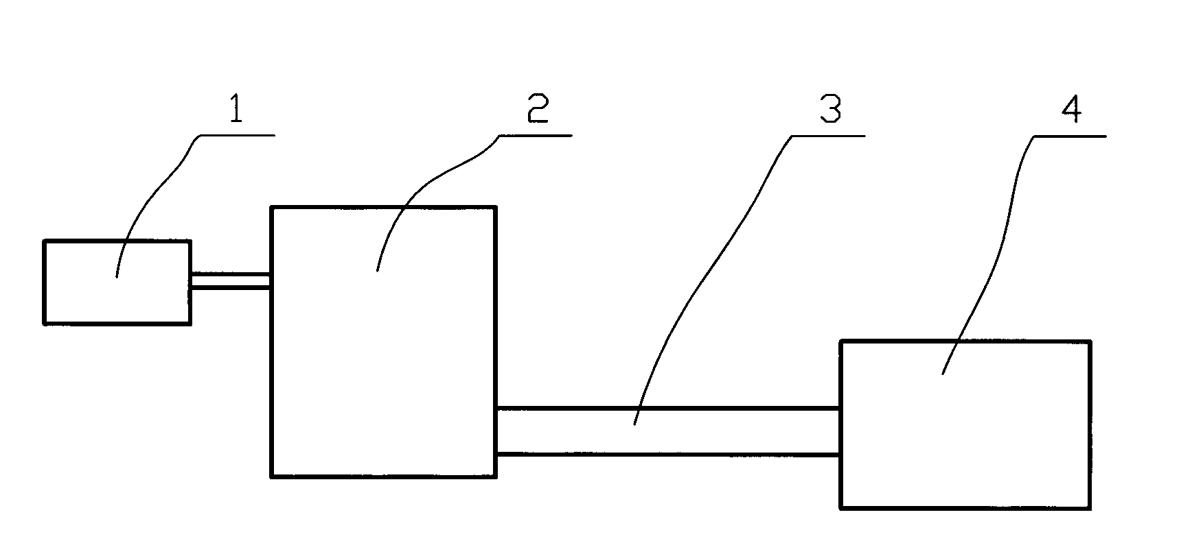
[0026] exist figure 1 , we can see that when the servo motor 1 starts to rotate, if the figure 1 The gears in the gear box 4 in the middle are well matched, then it is required to start from the output shaft of the motor and the input shaft of the gearbox, the middle gearbox 2, the large transmission shaft 3 and the large transmission shaft 3 and There must be better transmission rigidity between the gear shafts 7, so as to avoid the occurrence of crawling during the operation of the whole system.

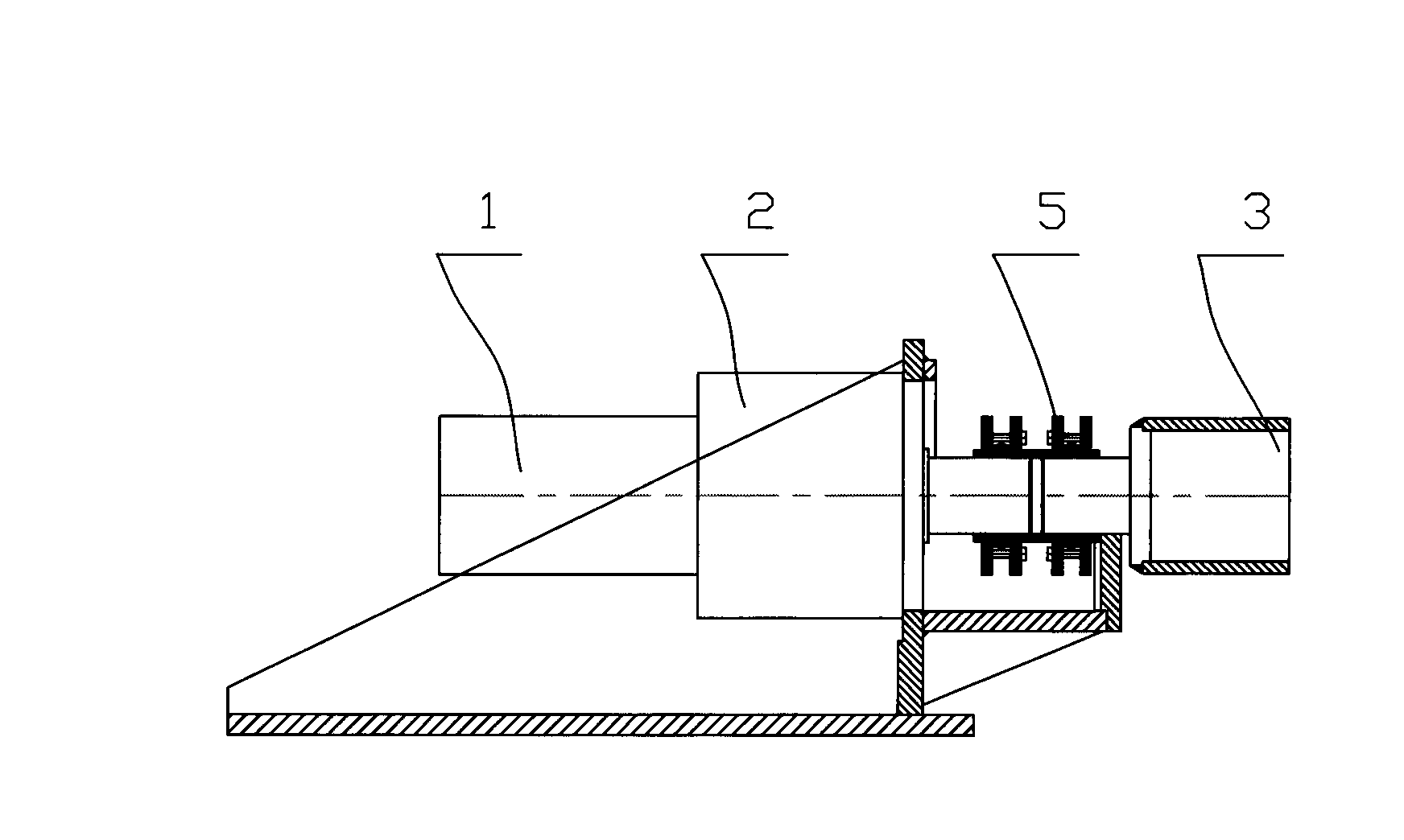
[0027] Such as figure 2 As shown, the output shaft of servo motor 1 and the input shaft of gearbox 2 are connected through expansion sleeves, which increases the transmission rigidity of the two parts. The output shaft of gearbox 2 and the shaft end of the large transmission shaft pass through the first An expansion sleeve 5 is connected, which also incr...


PUM


Abstract

The invention overcomes the defects of easy creeping and inaccurate positioning of the X-shaft when modifying a planing machine into a milling planer, and provides an X-shaft transmission system for modifying a planing machine into a milling planer, which has the advantages of simple structure and favorable positioning performance and comprises a driving motor, a gearbox and a large transmission shaft, wherein the gearbox is connected with the output shaft of the motor, and the large transmission shaft is connected with the gearbox. The system is characterized in that the other end of the large transmission shaft is connected with a gear shaft arranged in the gearbox body, the gear shaft is provided with a left gear and a right gear which cooperate with a rack on a workbench, and a spacerfor always keeping the left gear a certain distance away from the right gear is arranged between the left gear and the right gear. The invention has the advantages that the transmission system is modified on the basis of the prior system so as to save the resources; all segments of the transmission system are treated in a rigidity enhancement mode so as to well solve the creeping phenomenon of theX-shaft; and especially, the system adopts two gears to engage with the rack so as to eliminate the gap.

Description

technical field [0001] The invention relates to an X-axis transmission system in a gantry milling machine, in particular to an X-axis transmission system in which a gantry planer which can realize accurate and stable positioning of a workbench in the X-axis direction is transformed into a gantry milling machine. Background technique [0002] Machine tool manufacturers have produced tens of thousands of gantry planers for decades. The gantry planer motor has a large power, and the X-axis motor is one or two DC motors with a power of 60KW. A product that is phased out. Green remanufacturing of the planer—upgrading the planer to a milling machine can reduce the waste of materials and energy, re-use resources, and improve processing efficiency. About 75% of the weight of the machine tool can be reused, the efficiency of the machine tool can be increased by 3 to 6 times, and the energy saving can be more than 60%. Therefore, vigorously developing remanufacturing technology and ...

Claims


Application Information

Patent Timeline
Patent Type & Authority Applications(China)
IPC IPC(8): B23Q5/10B23Q5/12B23Q5/36
Inventor 朱德志郭建龙赵树涛韩欣谢沛青马长青
Owner 济南迈特力科技集团有限公司
Why Eureka
Try Eureka