
Urban rail tram

A technology of urban rail and tram, applied in the direction of electric vehicles, electric locomotives, locomotives, etc., can solve the problems of reduced service life, reduced service life, and disengagement, so as to save energy and ensure safety

Inactive Publication Date: 2010-03-10
周原 +1
View PDF4 Cites 12 Cited by
  • Summary
  • Abstract
  • Description
  • Claims
  • Application Information

AI Technical Summary

Problems solved by technology

The disadvantage of this prior art is that this scheme uses electromagnetic induction to transmit the electric energy on the power supply wire to the transport vehicle, thereby realizing the operation of the transport vehicle
As an electric vehicle, it is still two different modes of transportation compared with trams. Although the electric vehicle retains the mobility and flexibility of the car, it is precisely this feature that makes it run on the road because there is no running track. Due to the limitation of the conductive rail, the conductive rail is often out of contact with the sliding shoe, so that the electric vehicle is in the state of receiving power from the conductive rail for a while, and is in the state of being powered by the storage battery for a while. Frequent state transitions make It is difficult to maintain the normal driving of electric vehicles. In addition, the service life of the electrical equipment is greatly reduced due to the frequent change of working status; for the storage battery (battery), it is also in a state of discharging and charging for a while, which also greatly reduces its service life

Method used


Image

  • Urban rail tram
  • Urban rail tram
  • Urban rail tram

Examples


Embodiment 1

[0024] (Embodiment 1, urban rail car power supply system and urban rail car)

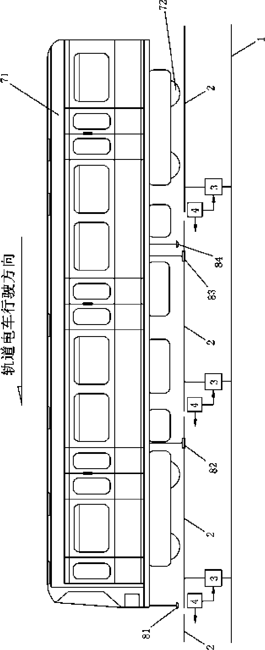
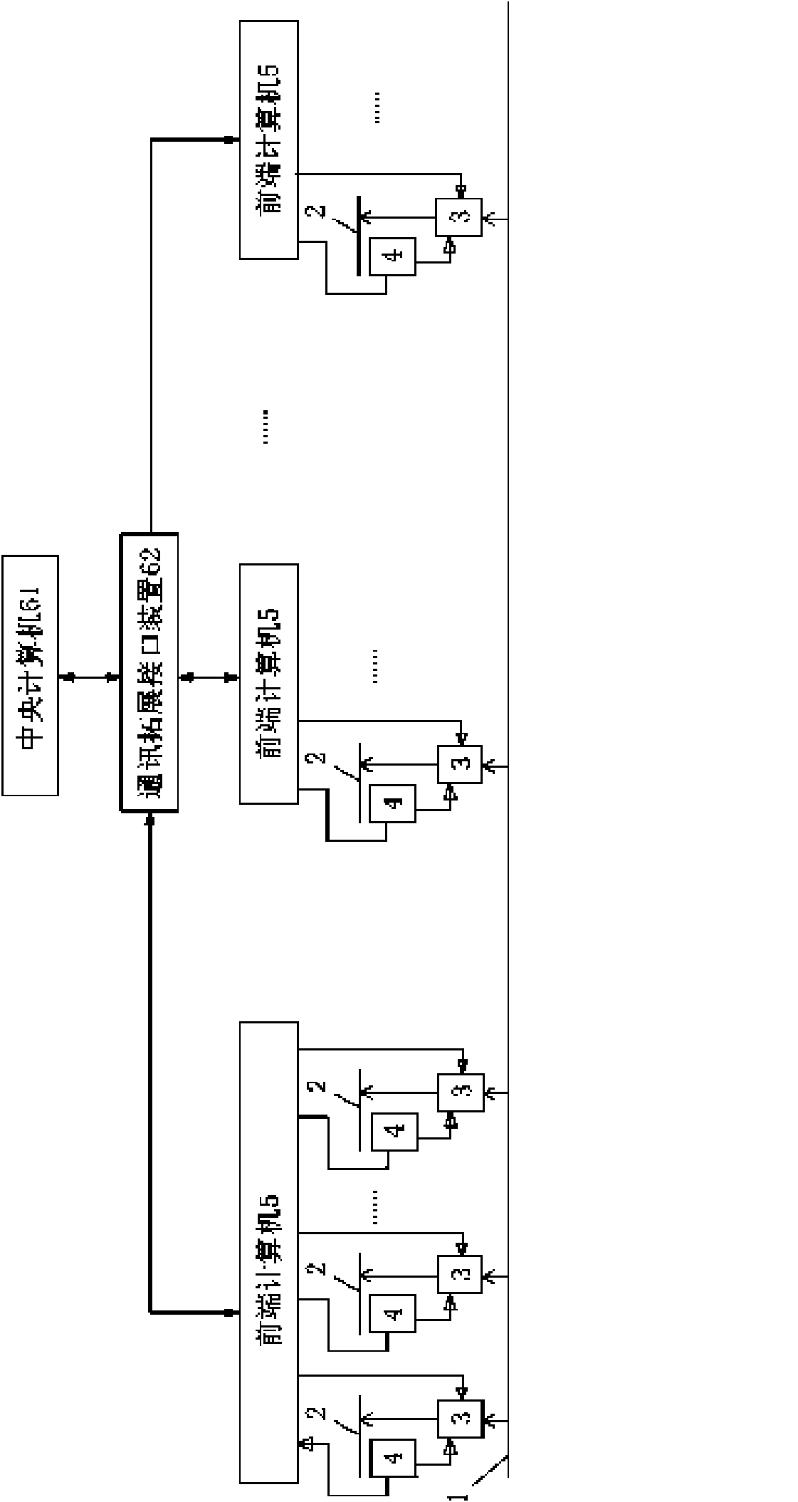
[0025] See figure 1 , figure 2 and Figure 4 , the power supply system for urban rail cars of the present embodiment includes a rail that is laid on the ground along the travel route and plays the role of the negative terminal of the power supply when used; Receive transponder 4, front-end computer 5, central computer 61.

[0026] The power supply cable 1 is continuously arranged under the surface of the whole traveling route and plays the role of the positive end of the electric power supply. The entire intermittent conductive rail is formed by laying all the conductive monorails 2 on the ground along the entire driving route, and the adjacent conductive monorails 2 are insulated from each other; the number of ground receiving transponders 4 is the same as the number of conductive monorails 2, and each Each ground transponder 4 is arranged near a corresponding conductive monorail 2 or fixed on...

Embodiment 2

[0061] (Embodiment 2, urban rail car power supply system and rail car)

[0062] See Figure 1 to Figure 4 On the basis of adopting the power supply system for urban rail cars in Embodiment 1, the power supply system for urban rail cars in this embodiment is further refined or preferably as follows.

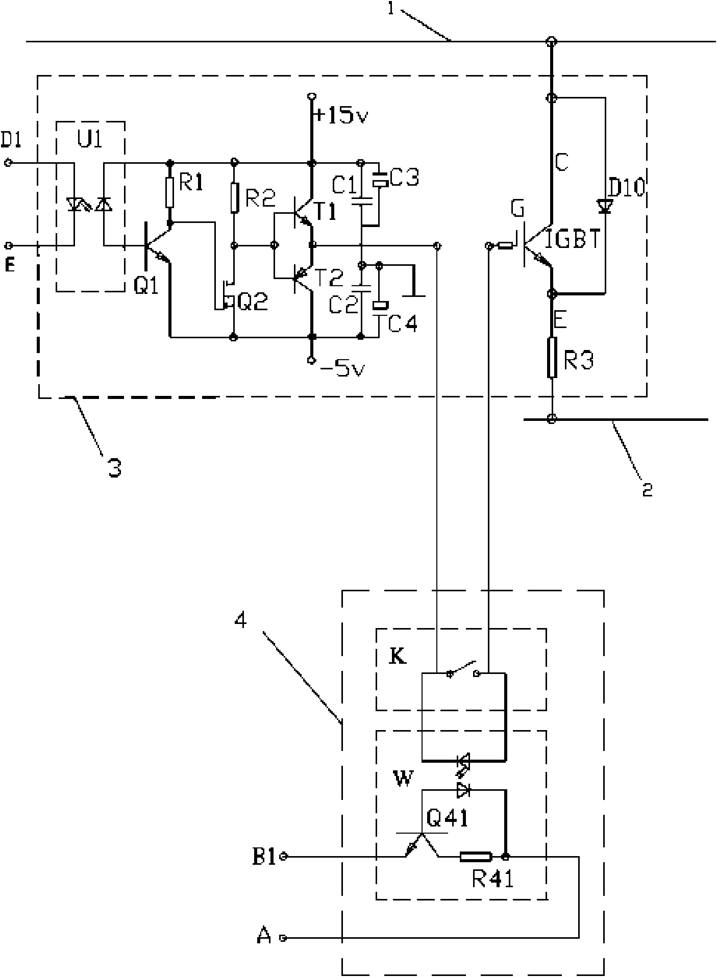
[0063] See image 3 , the ground transponder 4 is a high-frequency pulse transponder. The high-frequency pulse receiving transponder 4 includes an electronic high-frequency pulse switching device K and a photoelectric coupling device W with strong anti-interference ability and memory (self-locking) function.

[0064] The electronic high-frequency pulse switching device K has an on-off input terminal, an on-off output terminal and an on-off control terminal ( Figure 4 denoted by abbreviated symbols). The optocoupler W has an input loop and an output loop; the input loop includes a light emitting diode, and the output loop includes a photodiode, a transistor Q41 and a resistor ...

Embodiment 3

[0075] (Embodiment 3, urban rail car power supply system and urban rail car)

[0076] Most of the content of this embodiment is the same as that of Embodiment 2. On this basis, some of them are further refined as follows.

[0077] The tramcar of the present embodiment is a guide rail trolley. Railcars also have guides. The tram bogie of the railcar is a guide rail tram bogie; the tram bogie also has tires 72 for supporting the weight of the vehicle.

[0078] The guide device is arranged on the frame and is located under the front of the frame. The guide device has a guide wheel frame and 2 guide wheels; the guide wheel frame is fixed on the frame and is located below the frame, and each guide wheel is connected to the guide wheel frame in rotation. , and the two guide wheels are arranged obliquely opposite to each other. The negative terminal of the power supply of the tram electrical system is electrically connected with the guide wheel of the guide device.

[0079] The t...


PUM


Abstract

The invention relates to an urban rail tram which comprises a first vehicle-mounted control generator arranged on the tram and positioned below a frame, a first collector shoe, a second collector shoeand a second vehicle-mounted control generator, wherein the first vehicle-mounted control generator, the first collector shoe, the second collector shoe and the second vehicle-mounted control generator are arranged in sequence from beginning to end; when being used, the first collector shoe and the second collector shoe are both parts which are movably contacted with an electric conduction singlerail to realize electrical connection; the first vehicle-mounted control generator is positioned at the front end of the whole tram; the second vehicle-mounted control generator is positioned at themiddle part or the middle-back part of the whole tram; the first collector shoe is positioned at the front part of the whole tram; the second collector shoe is positioned between the middle part or the middle-back part of the whole tram; the first collector shoe is electrically connected with the second collector shoe; and the first collector shoe is electrically connected with an electrical system of the tram.

Description

technical field [0001] The invention relates to an urban rail car. Background technique [0002] Compared with buses using gasoline or diesel engines, the use of trams as a means of public transportation on the ground roads of modern cities has the advantages of environmental protection, energy saving and safety, and can make the control performance more perfect, and the characteristics of humanization and individualization are more obvious. Compared with other energy sources, electric energy can be obtained by renewable methods (such as wind energy, solar energy, etc.), which is not only inexhaustible, but also clean and environmentally friendly. [0003] Because electric power must be delivered by the power grid when the tram is running, a traction power grid that is continuously charged along the entire line is erected in the space above the road along the driving route. There are two power transmission methods for the traction grid. One way is that the traction grid its...

Claims


Application Information

Patent Timeline
IPC IPC(8): B61C3/00B60L5/38
CPCY02T30/40
Inventor 周原关湘亭
Owner 周原
Learn More