
Novel turbocharger

A turbocharger, a new type of technology, applied in the direction of machines/engines, gas turbine devices, engine components, etc., to simplify the sealing system, reduce the difficulty of machining, and improve reliability

Inactive Publication Date: 2010-03-10
CRRC DALIAN INST CO LTD
View PDF0 Cites 0 Cited by
  • Summary
  • Abstract
  • Description
  • Claims
  • Application Information

AI Technical Summary

Problems solved by technology

[0005] The invention provides a novel turbocharger, which adopts a magnetic bearing structure instead of an oil lubricating structure, which solves the technical problems of bearing quality and oil-air seal effect existing in the existing turbocharger

Method used


Image

  • Novel turbocharger
  • Novel turbocharger
  • Novel turbocharger

Examples


Embodiment Construction

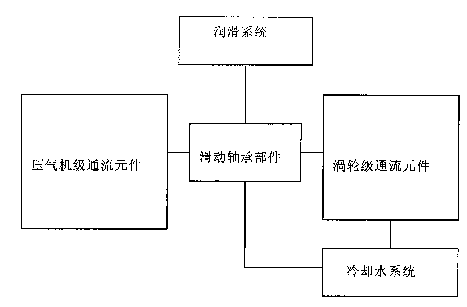
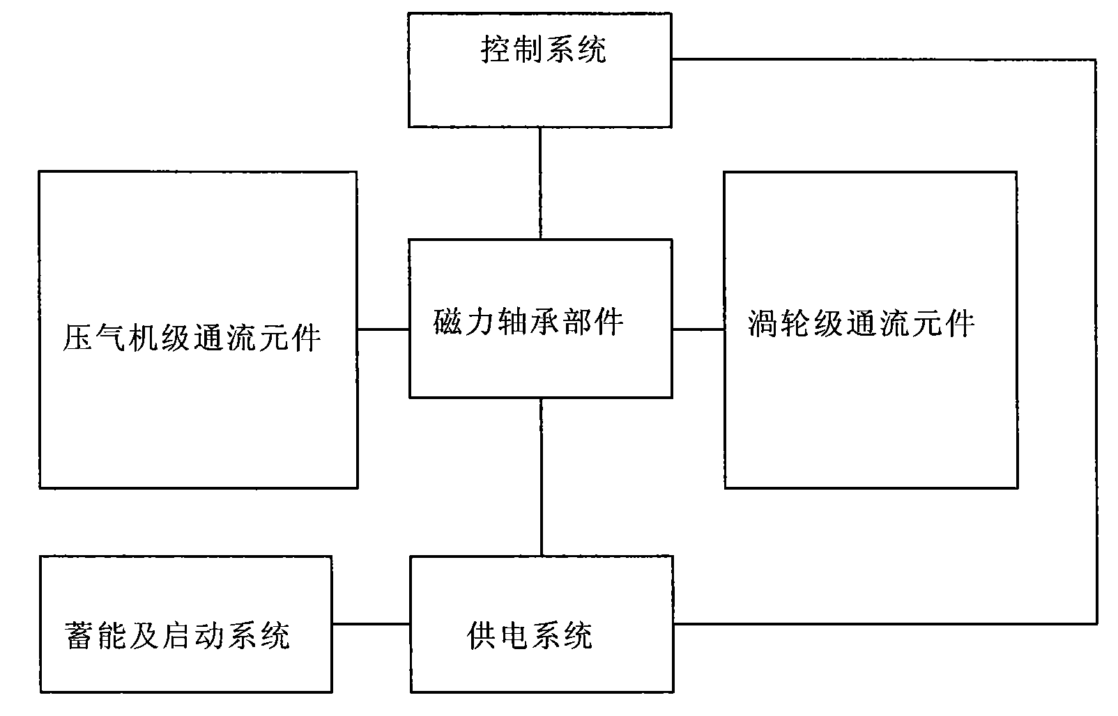
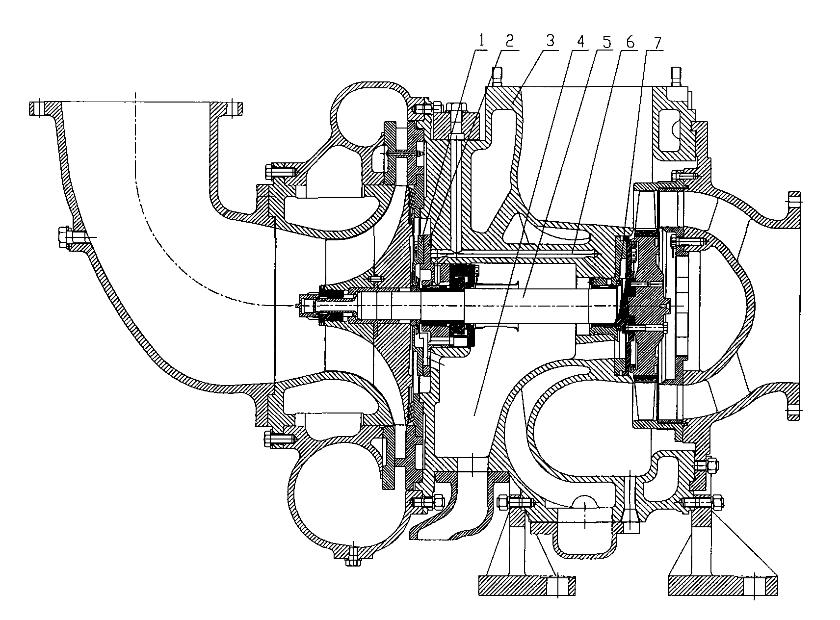
[0017] Such as figure 2 As shown, the structure of the new turbocharger module is: the compressor stage flow element and the turbine stage flow element are respectively located on both sides of the magnetic bearing component, and the compressed air component in the compressor flow element module is the compressor impeller and the turbine flow element. The power turbine in the flow element is connected by the shaft of the magnetic bearing component, which makes the shaft suspended in the center under the action of magnetic force, and the supercharger does not need oil lubrication, water cooling, or oil sealing. The compressor-level flow elements and the turbine-level flow elements form their own independent flow pipelines, and only need to seal the gases in the independent pipelines accordingly, so there are no problems such as blow-by gas, oil leakage and carbon deposits.

[0018] Depend on image 3 , 4 The difference between the existing turbocharger structure and the new ...


PUM


Abstract

The invention discloses a novel turbocharger which adopts a magnetic bearing and solves the problems of bearing quality and oil-gas sealing effect of the existing supercharger. A supercharger module structure is provided with a magnetic bearing part arranged between a compressor stage throughflow element and a turbine stage throughflow element; and a compressor impeller of a compression air part in the compressor stage throughflow element is axially connected with a power turbine in the turbine stage throughflow element through a magnetic bearing, the compressor stage throughflow element and the turbine stage throughflow element respectively form a self circulating sealed pipeline to seal the self gas; and the magnetic bearing part is connected with a power supply system, a control systemmodule is connected with the power supply system and the magnetic bearing part, and the power supply system is connected with an energy storage and starting system. The novel turbocharger has the advantages of simplifying the supercharger structure and the sealing system, improving the reliability, reducing the mechanical machining difficulty of the supercharger and being propitious to environmentprotection and safe running.

Description

technical field [0001] The invention relates to a turbocharger, in particular to a novel turbocharger. Background technique [0002] With the development of my country's transportation industry, the load of internal combustion engines has increased, and the faults of turbochargers have also increased sharply. The faults of existing turbochargers are mainly concentrated in oil seal leakage, bearing burning, and rotor solidification. It accounts for 60% to 70% of the total failure rate of the turbocharger, and the bearing burning failure accounts for about 50% of the total failure rate of the turbocharger. The cause of bearing burning can be summarized into three factors: oil product, oil pressure and bearing quality, and the first two items are related to the oil lubrication structure; in addition, due to the use of oil lubrication, the oil and gas seal cannot provide a good seal for the moving parts Effect, causing oil seal leakage or carbon deposit solid death. [0003] Su...

Claims


Application Information

Patent Timeline
Patent Type & Authority Applications(China)
IPC IPC(8): F01D25/16F02B39/00F02B37/00F02C6/12
CPCY02T10/144
Inventor 吕红卫张小峰
Owner CRRC DALIAN INST CO LTD
Learn More