Fully-automatic oily sewage filtration-type separator and separating system

A separator, oily sewage technology, applied in the direction of filtration separation, gravity filter, loose filter material filter, etc., can solve the problems of equipment investment, increased floor space, uneconomical water treatment, etc. More thorough cleaning and better recoil effect

Inactive Publication Date: 2010-03-17
深圳市兰科环境技术有限公司
View PDF2 Cites 25 Cited by
  • Summary
  • Abstract
  • Description
  • Claims
  • Application Information

AI Technical Summary

Problems solved by technology

Although the technology disclosed by the applicant's Chinese invention patent CN 100352533C "on-line self-recoiling high-precision fast filter and filtration system" can be used, its advantage is that special fiber filter material is used as the filter material, and oil stains will not adhere to the filter material. On the one hand, oil stains are easily removed during recoil, and there will be no blockage failure due to oil stain adsorption and saturation, but equipment investment and floor space will greatly increase, which is uneconomical when the amount of water to be treated is small
[0009] At present, there is no one in the market that can not only guarantee the high precision of oil-water separation, the oil content of the effluent water can reach 10mg / L or lower, and the filtration precision of the suspended solids (SS) in the effluent can reach ≤20mg / L; On-line automatic backwash (that is, no need to set up a backwash pool and backwash pump system) filter equipment

Method used


Image

  • Fully-automatic oily sewage filtration-type separator and separating system
  • Fully-automatic oily sewage filtration-type separator and separating system
  • Fully-automatic oily sewage filtration-type separator and separating system

Examples


Embodiment Construction

[0033] The present invention will be described in further detail below in conjunction with each accompanying drawing.

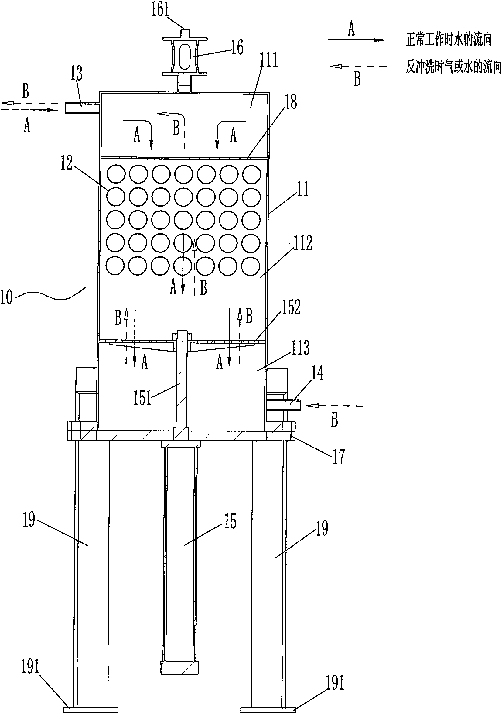
[0034] see figure 1 , a fully automatic oily sewage filter separator 10, comprising a tank body 11 and a filter material 12 in it, a water inlet 13, a water outlet 14, a cylinder 15, a pressure plate 152 fixed on the front end of the cylinder 15 piston rod 151, a device There are oil collector 16 of oil discharge port 161, cylinder fixed cover 17 and perforated partition 18, and this perforated partition 18 is provided with a plurality of through holes that allow oily sewage to flow through, and the size of each through hole must ensure that oily sewage Sewage and oil drop particles can pass through smoothly; the inner cavity of the tank body 11 includes a first chamber 111, a second chamber 112 and a third chamber 113; the water inlet 13 and the oil collector 16 are located in the The upper part of the tank body 11 is in communication with the first chamber...


PUM

PropertyMeasurementUnit
diameteraaaaaaaaaa
diameteraaaaaaaaaa

Abstract

The invention relates to a fully-automatic oily sewage filtration-type separator which comprises a tank body, filter material, a water inlet, a water outlet, a cylinder, a pressure plate, an oil collector, a cylinder fixing cover for fixing the cylinder, and a perforated clapboard; a first chamber is formed between the perforated clapboard and the top wall of an inner cavity of the tank body; thewater inlet and the oil collector are arranged at the upper part of the tank body and both communicated with the first chamber; the perforated clapboard is arranged at the upper part of the inner cavity of the tank body and below the water inlet; the cylinder fixing cover is fixed with the lower end of the tank body, and a piston rod of the cylinder passes through the cylinder fixing cover and then extends into the inner cavity of the tank body; a third chamber is formed between the cylinder fixing cover and the pressure plate; the water outlet is arranged at the lower part of the tank body and communicated with the third chamber; a second chamber is formed between the pressure plate and the perforated clapboard, and a filter core is arranged in the second chamber. The invention also relates to a separating system which adopts the fully-automatic oily sewage filtration-type separator. The invention has small occupying area, is unnecessary to filter oily sewage in advance, can not onlyensure high oil-water separation precision, but also carry out automatic backwash on line.

Description

【Technical field】 [0001] The invention relates to sewage treatment technology, in particular to a device and system for high-precision and fast filtering of oily sewage. 【Background technique】 [0002] The prior art oil-water separator can include four kinds of separation principles: gravity method, adsorption method, membrane separation method and coarse graining method: [0003] The first, the gravity method, is based on the Stock's principle for oil-water separation. That is to use the different specific gravity of oil and water, and use some technical means to make tiny oil stains grow up, float and separate. Commonly used equipment includes: gravity grease trap, inclined plate grease trap, air flotation, etc. This method cannot separate the emulsified oil, the separation effect and efficiency are poor, and the separation accuracy is generally around 30mg / l. However, due to the simplicity of this method, it is currently the main means of oil-water separation and is us...

Claims


Application Information

Patent Timeline
Patent Type & Authority Applications(China)
IPC IPC(8): B01D17/022B01D24/12B01D24/46
Inventor 洪川
Owner 深圳市兰科环境技术有限公司
Why Eureka
Try Eureka