Fill type stirring friction plug repair welding method and welding tool thereof

A friction stir and filling technology, applied in welding equipment, manufacturing tools, non-electric welding equipment, etc., can solve problems such as poor mechanical properties and reduced strength of welded joints, achieve small workpiece deformation, ensure one-time forming, and process stability. and high reproducibility

Inactive Publication Date: 2010-03-17
HARBIN INST OF TECH
View PDF0 Cites 49 Cited by
  • Summary
  • Abstract
  • Description
  • Claims
  • Application Information

AI Technical Summary

Problems solved by technology

[0003] The purpose of the present invention is to solve the problems of welding seam defects and welding seam keyholes in friction stir welding, which are repaired by fusion welding or fri...

Method used


Image

  • Fill type stirring friction plug repair welding method and welding tool thereof

Examples


specific Embodiment approach 1

[0008] Specific embodiment one: this embodiment is realized through the following steps: one, the selection of the material of the stirring pin: the material of the stirring pin is the same as the material of the parts to be repaired; Make a positioning hole at the welding seam defect or the keyhole of the welding seam, and use a type drill to expand the positioning hole into a tapered hole according to the repair welding requirements, which is the preset hole for repairing the defect to be repaired; 3. Determine the size of the stirring needle: Stir The outer contour size of the needle should be larger than the inner contour size of the tapered defect repair preset hole to ensure that the stirring needle and the defect repair preset hole have sufficient friction and sufficient filling volume; 4. Positioning: positioning the defect repair preset hole , so that the defect repair preset hole coincides with the axis of the stirring pin; 5. Repair welding: the moving length of the ...

specific Embodiment approach 2

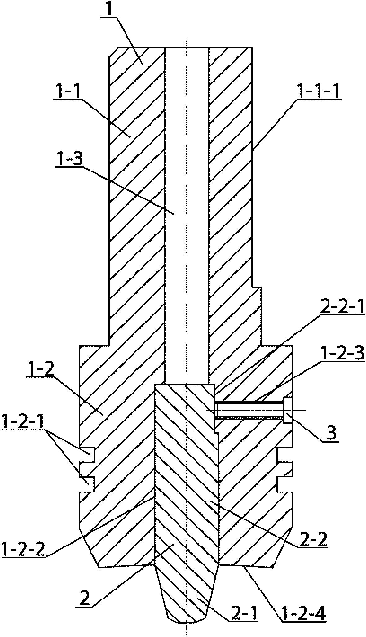
[0009] Specific implementation mode two: combination figure 1 Describe this embodiment, this embodiment includes a welding tool holding body 1 and a stirring body 2, the welding tool holding body 1 is composed of a coaxial upper cylinder 1-1 and a lower cylinder 1-2, the upper cylinder The diameter of 1-1 is smaller than the diameter of the lower cylinder 1-2, the upper cylinder 1-1 and the lower cylinder 1-2 are integrated, and the outer surface of the upper cylinder 1-1 is provided with a welding tool clamping surface 1 -1-1, at least one annular heat insulation groove 1-2-1 is provided on the outer surface of the lower cylinder 1-2, and a clamp for placing the stirring body 2 is provided at the center of the lower end of the lower cylinder 1-2 Holding hole 1-2-2, the side wall of the holding hole 1-2-2 of the lower cylinder 1-2 is provided with a threaded through hole 1-2-3 perpendicular to the axis of the lower cylinder 1-2, the stirring body 2. It consists of a stirring ...

specific Embodiment approach 3

[0010] Specific implementation mode three: combination figure 1 To illustrate this embodiment, the lower end surface of the lower cylinder 1-2 in this embodiment is a concave shoulder surface 1-2-4 whose outer edge is higher than the center. The concave shoulder surface 1-2-4 effectively prevents the plasticized material from the stirring needle 2-1 from flowing out. Other components and connections are the same as those in the second embodiment.


PUM


Abstract

The invention discloses a fill type stirring friction plug repair welding method and a welding tool thereof, and relates to a stirring friction plug repair welding method and a welding tool thereof. The invention adopts fusion welding or friction plug welding for repair welding and causes the welding joints to reduce strength and have poor mechanical performance. The method comprises the followingsteps: (1) the material of a stirring pin is same as that of the part which repairs welding; (2) a conical preset hole is opened; (3) the size of the stirring pin is determined; (4) positioning is carried out; and (5) welding of the stirring friction plug is repaired. The welding tool is characterized in that the side wall of a clamping hole of a lower cylinder is provided with a thread through hole; a stirring body consists of the stirring pin and a stirring pin seat which are combined into a whole from top to bottom; the outer surface of the stirring pin seat is provided with a stirring pinclamping surface; the stirring pin is a cone; the stirring body is arranged in the clamping hole on the lower cylinder; the stirring pin clamping surface aligns to the thread through hole; and the stirring pin is exposed at the outside of the lower end surface of the lower cylinder. The invention is used for repair welding of the weld defects of stirring friction welding and keyholes.

Description

technical field [0001] The invention relates to a friction stir welding method and a welding tool thereof, which are used for repair welding of friction stir welding seam defects and keyholes. Background technique [0002] Since the British Welding Institute (TWI) invented the friction stir welding method in 1991, this technology can eliminate welding defects such as pores, inclusions, cracks, etc. And it does not produce arc light, smoke, noise pollution, etc., and at the same time can significantly reduce costs, save materials, optimize structures, and reduce the structural weight of aircraft, etc., which have attracted the attention of scientific research institutions in various countries. Because this technology has many remarkable features that other methods do not have, it will soon be used in the aerospace field, and this method is selected for the welding of the longitudinal seam of the core tank section of the new generation of launch vehicles. Although the frictio...

Claims


Application Information

Patent Timeline
IPC IPC(8): B23K20/12B23K20/24
Inventor 黄永宪冯吉才吕世雄刘会杰田英韩冰吴建飞范煊赫石俊秒
Owner HARBIN INST OF TECH
Why Eureka
Try Eureka