
Rocket movable launcher supporting arm speed reducer

A movable platform and rocket launching technology, which is applied in the direction of rocket launching devices, weapon types, transmission devices, etc., can solve the problems of incomplete satisfaction, low transmission efficiency, and small maximum allowable torque, so as to shorten the axial size and ensure transmission Stiffness, Effects of Radial Dimension Reduction

Active Publication Date: 2011-04-13
ZHENGZHOU RES INST OF MECHANICAL ENG CO LTD
View PDF0 Cites 0 Cited by
  • Summary
  • Abstract
  • Description
  • Claims
  • Application Information

AI Technical Summary

Problems solved by technology

The maximum allowable torque of the reducer with this structure is small, the transmission efficiency is low, and η<70%, so it cannot fully meet the above performance requirements

Method used


Image

  • Rocket movable launcher supporting arm speed reducer
  • Rocket movable launcher supporting arm speed reducer

Examples


Embodiment Construction

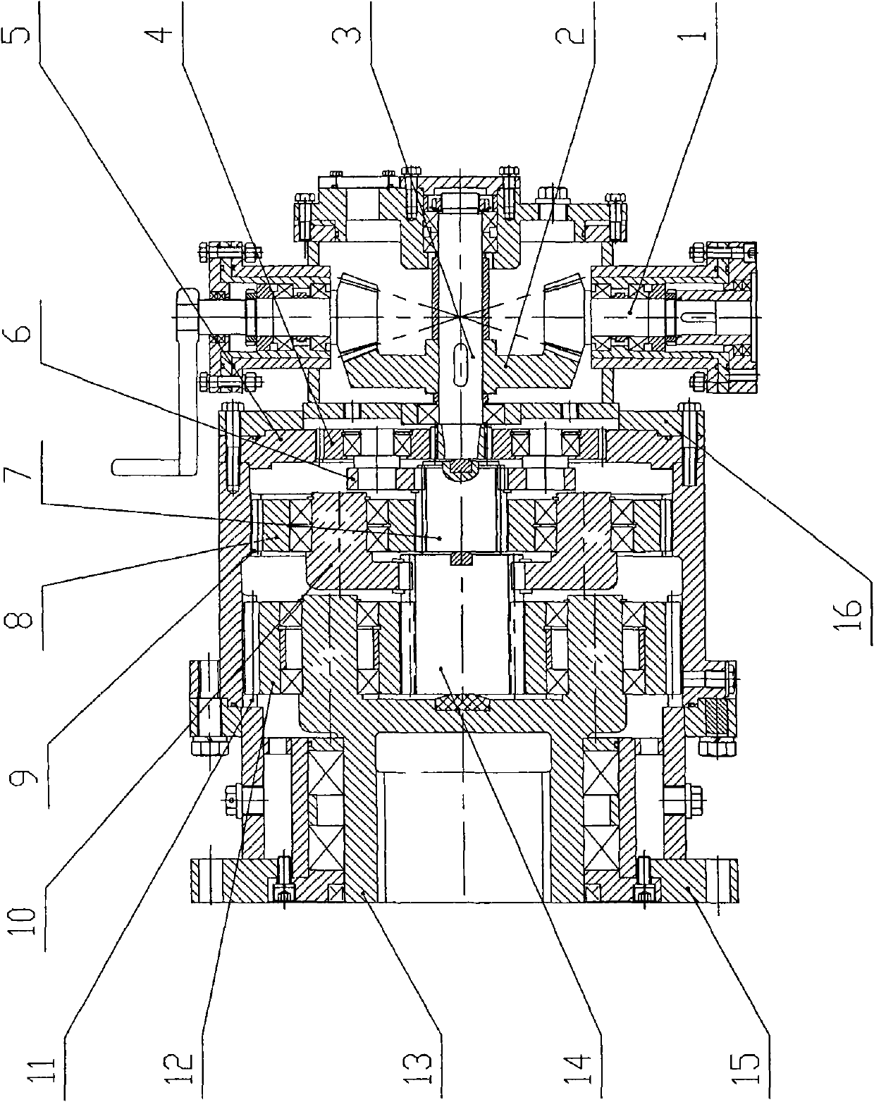
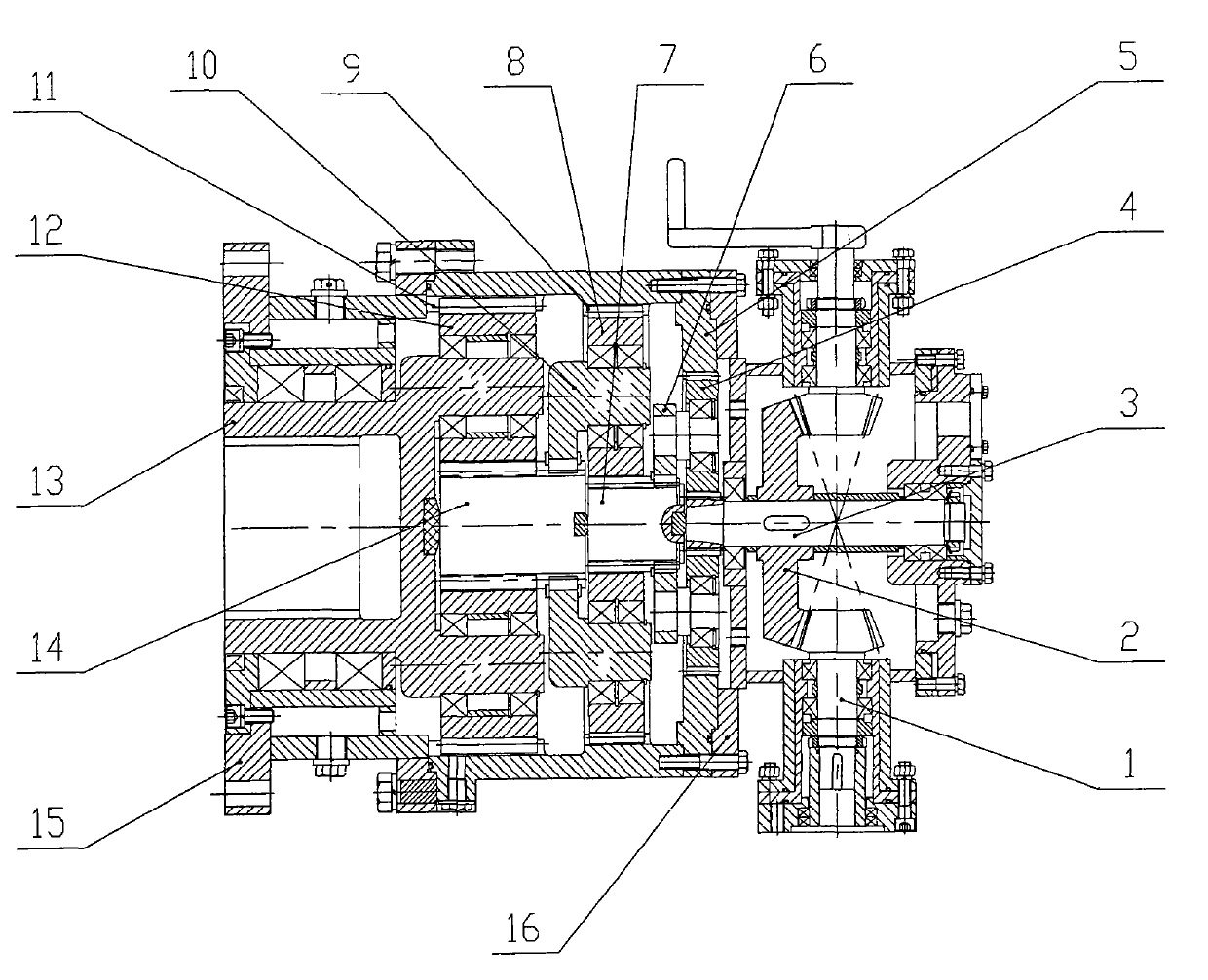
[0011] As shown in the figure, the rocket launch movable platform support arm reducer of the present invention includes input and output boxes 16, 15, input bevel gear pairs, and are composed of sun gear, planetary gear, planetary carrier, and ring gear respectively. The three-stage planetary gear train;

[0012] a. The input bevel gear shaft 1 of the input bevel gear pair extends out of the input box 16, the large bevel gear 2 is installed on the first-stage sun gear 3 shaft, and the input bevel gear shaft 1 and the first-stage sun gear 3 shaft pass through The front and rear bearing supports are positioned in the input box 16, and the motion and power are transmitted to the first-stage planetary gear train through the three-axis first-stage sun gear;

[0013] b. The outer surface of the ring gear 5 of the first-stage planetary gear train is used as a part of the box, and is connected to the input box 16, and the ring gears 9 and 11 of the second and third-stage planetary gea...


PUM


Abstract

The invention discloses a rocket movable launcher supporting arm speed reducer. The speed reducer comprises an input case, an output case, an input bevel gear pair and a three-stage planetary gear train, wherein the bevel gear shaft of the input bevel gear pair extends to the outside of the input case, a bevel gear wheel is arranged on a one-stage sun gear shaft, the input bevel gear shaft and the one-stage sun gear shaft are arranged in the case and supported and positioned by bearings, the outer surface of a one-stage annular gear is used as a part of the case and separately connected with the input case and two-stage and three-stage annular gears through connecting pieces, the two-stage and three-stage annular gears have integral structures, a one-stage planet gear is arranged on a one-stage planet carrier and supported by bearings, the outer surface of the two-stage and three-stage annular gears is used as a part of the case, the two ends of the annular gears are coupled with the output case and the one-stage annular gear, a three-stage planetary gear is arranged on a three-stage planet carrier and supported by bearings, a three-stage sun gear is arranged in a floated manner, and the three-stage planet carrier is used to output the motion and powder. The invention has the advantage of high efficiency and small volume.

Description

technical field [0001] The invention relates to a speed reducer, in particular to a speed reducer for a support arm of a rocket launching movable platform. Background technique [0002] The support arm reducer of the rocket launch platform must have high reliability, long life, high efficiency, small size, large output torque, low operating speed, large speed ratio, and high transmission rigidity. At present, the deceleration device used in the support arm of the rocket launch platform in our country is a close-to-round movable tooth reducer, which belongs to the differential transmission with few movable teeth. The maximum allowable torque of the reducer with this structure is small, the transmission efficiency is low, and η<70%, so it cannot fully meet the above-mentioned performance requirements. Contents of the invention [0003] The purpose of the present invention is to provide a support arm reducer for a rocket launching movable platform with compact structure, ...

Claims


Application Information

Patent Timeline
Patent Type & Authority Patents(China)
IPC IPC(8): F16H1/32F16H1/46F41F3/04
Inventor 李志胜刘世军刘海波杜宗禄张洪战丁鹏飞
Owner ZHENGZHOU RES INST OF MECHANICAL ENG CO LTD
Learn More