Method for quickly measuring circuit power consumption
A technology for measuring circuit and power consumption, applied in the direction of electric power measurement through current/voltage, etc., can solve problems such as many 0 ohm resistances, it is difficult to achieve non-destructive measurement of mobile phone PCBs, and it is difficult to test the supply current of multiple power supplies at the same time. , to achieve the effect of rapid positioning and confirmation, speeding up R&D and maintenance
- Summary
- Abstract
- Description
- Claims
- Application Information
AI Technical Summary
Problems solved by technology
Method used
Image
Examples
Embodiment 1
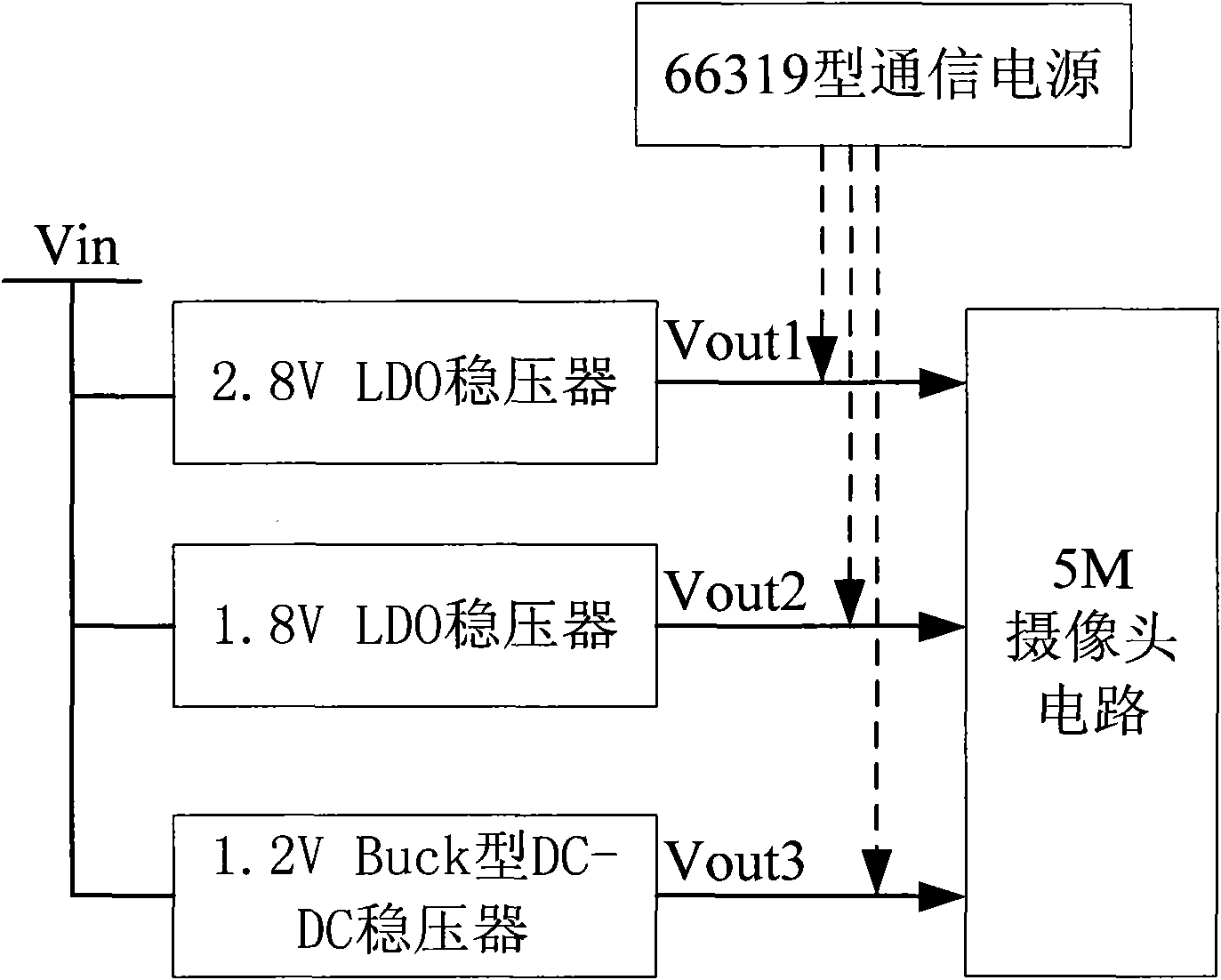
[0038] Embodiment one, see image 3 As shown, in this embodiment, the 5-megapixel camera circuit inside the mobile phone is used as a load to measure its power consumption in each power supply domain.
[0039] Such as image 3 As shown, the power supply circuit of the 5-megapixel camera circuit includes three voltage regulators, and the required supply voltages (namely the nominal output voltage) are 2.8V, 1.8V and 1.2V respectively. In order to improve the conversion efficiency, the 1.2V voltage is provided by the conversion output of the Buck type DC-DC voltage regulator, and the other two voltages are provided by the conversion output of the 2-way LDO voltage regulator. The input voltages of the three voltage regulators all adopt the Vin voltage, and the actual output voltages are recorded as Vout1, Vout2, and Vout3 respectively.
[0040] During the debugging process of the camera circuit, if you need to know the working current of the current three voltage domains, first...
Embodiment 2
[0047] Embodiment 2, still taking the 5-megapixel camera circuit inside the mobile phone as an example for illustration, see Figure 4 shown.
[0048] The 2.8V, 1.8V, and 1.2V power supplies required by the 5-megapixel camera circuit are respectively drawn from the printed circuit board (PCB) where they are located through test points. The test points are preset pads on the PCB, and each pad is connected to the voltage output terminals of each voltage regulator in one-to-one correspondence when the PCB is printed, that is, the voltage value of each pad is the three-way stabilizer. The actual output voltage value of the transformer. The triple regulator can be used as image 3 The design and implementation of the three-way voltage regulator shown in the present embodiment will not be repeated here.
[0049] The PCB board is fixed by a tool, and a plurality of probes are installed on the tool, and are respectively connected to each test point one by one through the plurality ...
PUM
 Abstract
Description
Claims
Application Information
 - R&D
- Intellectual Property
- Life Sciences
- Materials
- Tech Scout
- Unparalleled Data Quality
- Higher Quality Content
- 60% Fewer Hallucinations
Browse by: Latest US Patents, China's latest patents, Technical Efficacy Thesaurus, Application Domain, Technology Topic, Popular Technical Reports.
© 2025 PatSnap. All rights reserved.Legal|Privacy policy|Modern Slavery Act Transparency Statement|Sitemap|About US| Contact US: help@patsnap.com


