
Zoom lens and camera device

A zoom lens and lens technology, applied in image communication, television, optics, etc., can solve the problems of insufficient miniaturization of the lens system, large movement of the second lens group, and easy to increase the diameter of the front lens, etc. Effects of miniaturization, shortening, and increase in manufacturing errors

Inactive Publication Date: 2010-03-17
FUJI PHOTO OPTICAL CO LTD
View PDF5 Cites 2 Cited by
  • Summary
  • Abstract
  • Description
  • Claims
  • Application Information

AI Technical Summary

Problems solved by technology

[0010] The zoom lens described in Patent Document 4 has a 15-lens structure in the entire system, which is not sufficient from the viewpoint of miniaturization of the total length of the lens system in the optical axis direction.
The zoom lens described in Patent Document 5 uses a composite aspheric lens in the second lens group, and the second lens group cannot have such a large negative refractive power. Therefore, the movement amount of the second lens group is large, and there is light Concerns about enlargement of the lens system in the axial direction
[0011] In addition, the zoom lens described in Patent Document 5 cannot bring the object-side principal point of the second lens group too close to the object side, so the diameter of the front lens tends to be large.
In order to reduce the diameter of the front lens, it is necessary to study the structure of the second lens group. In this regard, the zoom lenses described in Patent Documents 1 to 3 have room for improvement.

Method used


Image

  • Zoom lens and camera device
  • Zoom lens and camera device
  • Zoom lens and camera device

Examples


Embodiment

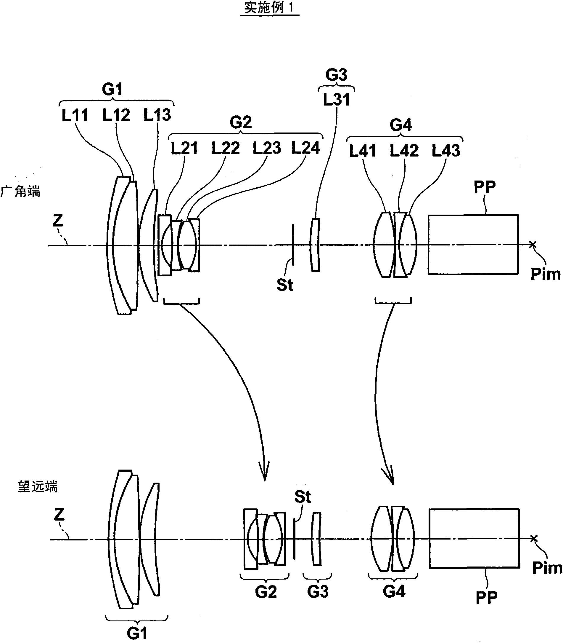
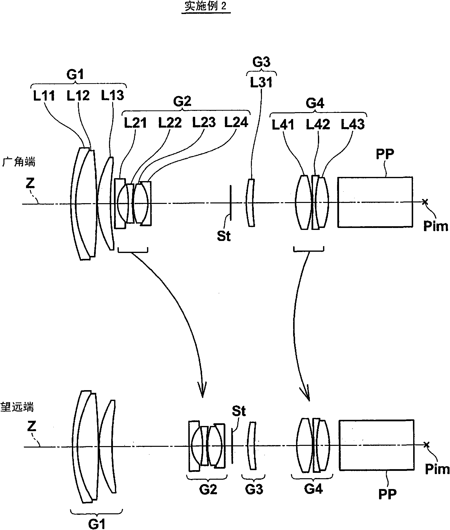
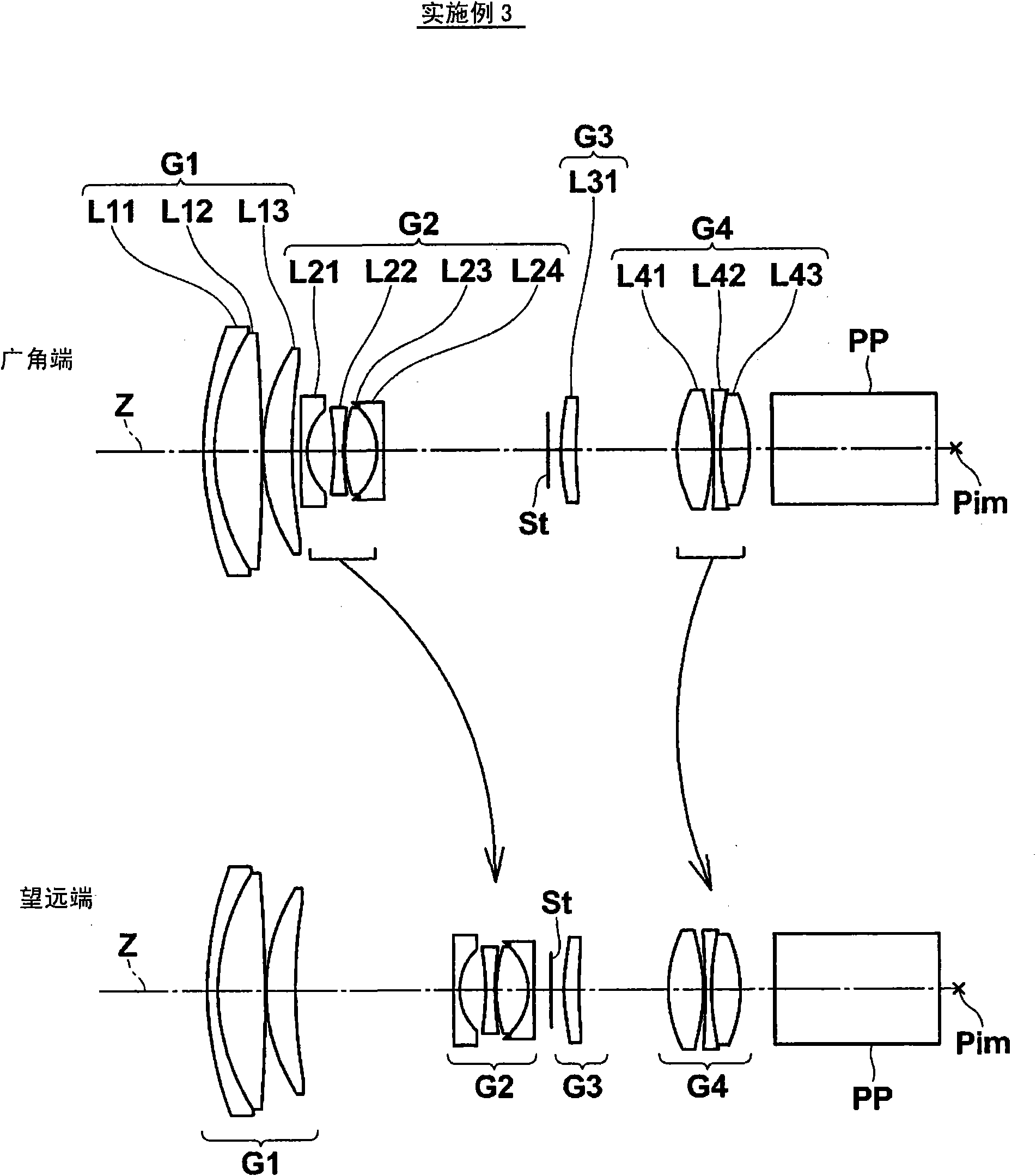
[0119] Next, specific numerical examples of the zoom lens of the present invention will be described. exist figure 1 A lens sectional view of the zoom lens of Example 1 is shown. exist Figure 2 to Figure 8 Each lens sectional view of the zoom lens of Examples 2-8 is shown, respectively. Figure 2 to Figure 8 The graphical method and figure 1 same.

[0120] Table 1 shows the basic lens data of the zoom lens according to Example 1, Table 2 shows the data related to zooming (magnification), and Table 3 shows the aspheric surface data. Similarly, Tables 4 to 24 show basic data, data related to zooming, and aspheric surface data of the zoom lenses according to Examples 2 to 8. Hereinafter, the meanings of the symbols in the tables will be described taking Example 1 as an example, but the same applies to Examples 2 to 8.

[0121] In the basic lens data in Table 1, Si represents the i-th (i=1, 2, 3, . Number, Ri indicates the radius of curvature of the i-th surface, and Di in...


PUM


Abstract

The invention provides a zoom lens, wherein the zoom lens realizes miniaturization of diameter of a front lens and shortens total length of the lens system in light axis direction apart from maintaining high optical performance. The zoom lens comprises four lens assemblies from a first lens assembly (G1) to a forth lens assembly (G4). The first lens assembly (G1) and the third lens assembly (G3) are fixed, and the second lens assembly (G2) is moved when zooms in or out, and the forth lens assembly (G4) is moved to correct image plane position of the zoom and focus. The first lens assembly (G1)comprises a negative lens and two positive lens. The second lens assembly (G2) comprises four lens with one negative lens having a aspheric surface. The following conditional expression (1), (2) aresatisfied: 6.0<f1 / fw<8.0 (1), 0.10<H2f / fw<0.20 (2). Further more, f1 means focal distance of the first lens assembly, fw means focal distance of the entire system on a wide-angle end, H2f means distance from object side of a lens that nearest to the object side of the second lens assembly to an light axis of a principal point on an object side of the second lens assembly.

Description

technical field [0001] The present invention relates to a zoom lens and an imaging device, and more specifically, to a zoom lens suitably used for a video camera, an electronic still camera, a surveillance camera, and the like, and an imaging device including the zoom lens. Background technique [0002] In the past, as zoom lenses used in consumer video cameras and the like, zoom lenses of the 4-group or 5-group type have been proposed many times. For example, Patent Documents 1, 2, and 3 disclose a zoom lens having a high zoom ratio of about 10 times and an F-number of about 1.8, including three lenses that constitute a second lens group that moves when zooming. Patent Document 4 discloses a 5-group type zoom lens including a total of 15 lenses that constitutes the second lens group with four lenses. Patent Document 5 discloses a zoom lens using a composite aspheric lens in which an aspheric resin is formed on a glass spherical surface. [0003] Patent Document 1: Japanes...

Claims


Application Information

Patent Timeline
Patent Type & Authority Applications(China)
IPC IPC(8): G02B15/16G02B1/04H04N5/225
Inventor 河村大树
Owner FUJI PHOTO OPTICAL CO LTD
Learn More