
Touch-control display panel and display device

A touch display panel and display device technology, applied in the direction of identification devices, static indicators, instruments, etc., can solve the problems of low screen printing process precision, reduction, and limited design space of display devices, etc., to achieve the expansion of display screen size, The effect of reducing resistance value and line width, and high process precision

Inactive Publication Date: 2013-04-17
AU OPTRONICS CORP
View PDF3 Cites 2 Cited by
  • Summary
  • Abstract
  • Description
  • Claims
  • Application Information

AI Technical Summary

Problems solved by technology

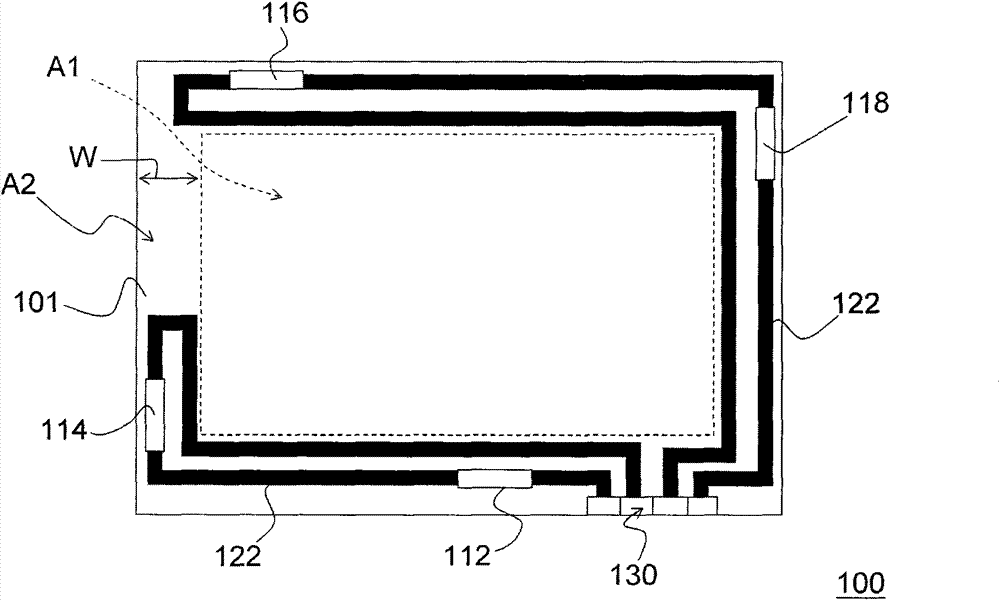
[0005] In addition, due to the low precision of the screen printing process, it is difficult to effectively reduce the line width of the transmission wires 122, and, in fact, the distance between the two transmission wires 122 must be greater than 0.1 mm at least.
In other words, the width W of the non-display area A2 of the touch panel 100 is bound to be further increased, which will result in poor space utilization of the product.
In addition, since the display device using the touch panel 100 must have the protection substrate 101, this also causes the design space of the display device to be limited.

Method used


Image

  • Touch-control display panel and display device
  • Touch-control display panel and display device
  • Touch-control display panel and display device

Examples


Embodiment Construction

[0050] touch display panel

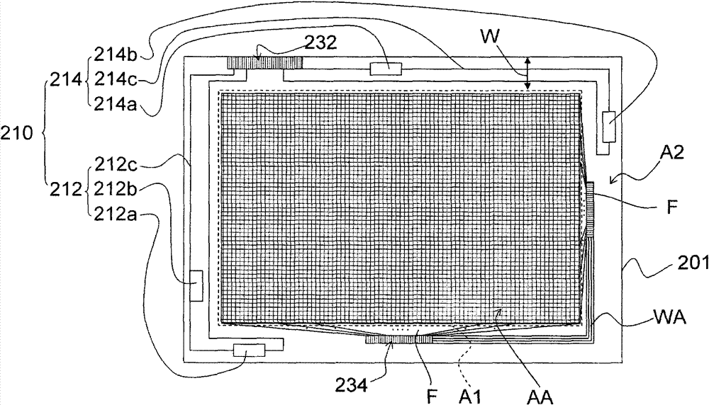
[0051] Figure 2A It is a schematic top view of a first substrate and components disposed on the first substrate in a touch display panel according to an embodiment of the present invention. Figure 3A It is a schematic side view of a touch display panel according to an embodiment of the present invention.

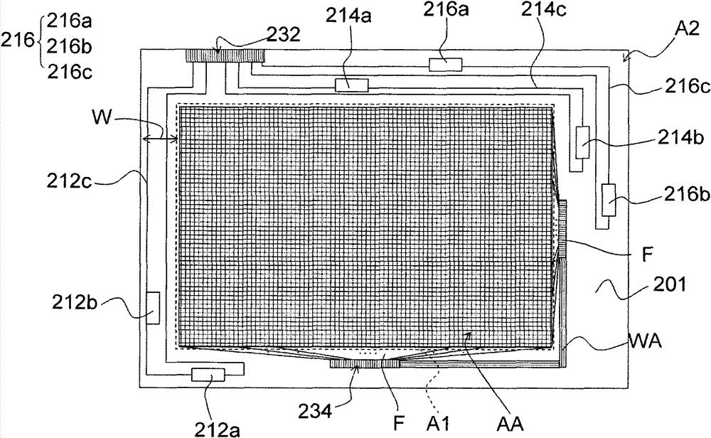
[0052] Please refer to Figure 2A , the touch component 210 is disposed on the first substrate 201 . The first substrate 201 has a display area A1 and a non-display area A2, and the non-display area A2 is located outside the display area A1. The touch component 210 is directly disposed on the first substrate 201 and located in the non-display area A2 , wherein the touch component 210 is composed of two sets of receiving components 212 , 214 .

[0053] Specifically, the receiving component 212 is composed of a piezoelectric component 212a, a piezoelectric component 212b and a transmission wire 212c, and the transmission wire 212c connects the ...


PUM

PropertyMeasurementUnit
widthaaaaaaaaaa

Abstract

The invention discloses a touch-control display panel and a display device. The touch-control display panel comprises a first substrate, a touch-control assembly and a display medium layer, wherein the first substrate is provided with a display area and a non-display area, and the non-display area is positioned outside the display area; the touch-control assembly is directly allocated on the first substrate and positioned in the non-display area, and the touch-control assembly at least comprises two sets of receiving assemblies; and the display medium layer is positioned in the display area. The touch-control display panel has high processing procedure precision and can reduce the resistance value and the width of the transmission wire. Since the display device is provided with the touch-control display panel, the width of the non-display area can be reduced so as to increase the size of the display screen of the product.

Description

technical field [0001] The present invention relates to a touch display panel and a display device, and in particular to a high-precision manufacturing process, low wire resistance, narrow non-display area width, low power consumption, and can be used for handwriting of conductors. and an insulating pen-written touch display panel and a display device. Background technique [0002] Currently, touch panel designs can be roughly classified into resistive, capacitive, optical, acoustic, and electromagnetic types. Among them, the acoustic wave touch panel mainly senses the sound after touching the panel for positioning, so no matter it is operated by handwriting, pen writing or wearing gloves, it can be recognized. In addition, when the size of the panel increases, the number of sensing components required by the acoustic wave touch panel does not need to increase, so the production cost of the product is lower. [0003] figure 1 It is a schematic top view of a known acoustic...

Claims


Application Information

Patent Timeline
Patent Type & Authority Patents(China)
IPC IPC(8): G02F1/133G06F3/041G09F9/30
Inventor 郭峻廷马玫生李国贤
Owner AU OPTRONICS CORP
Learn More