Laser scanning location device

A positioning device and laser scanning technology, applied in the direction of emergency protection devices, emergency protection device manufacturing, electrical components, etc., can solve the problems of automatic assembly, debugging, and detection, etc., and achieve convenient maintenance or replacement of guide sleeves and rapid action , The effect of high positioning accuracy

Inactive Publication Date: 2010-03-24
SHANGHAI UNIV OF ENG SCI
View PDF0 Cites 12 Cited by
  • Summary
  • Abstract
  • Description
  • Claims
  • Application Information

AI Technical Summary

Problems solved by technology

[0007] When the factory automates the production of low-voltage circuit breakers, it is necessary to perform three-dimensional positioning work in the links of assembly, debugging, and testing, so that automatic mech

Method used


Image

  • Laser scanning location device
  • Laser scanning location device
  • Laser scanning location device

Examples


Embodiment 1

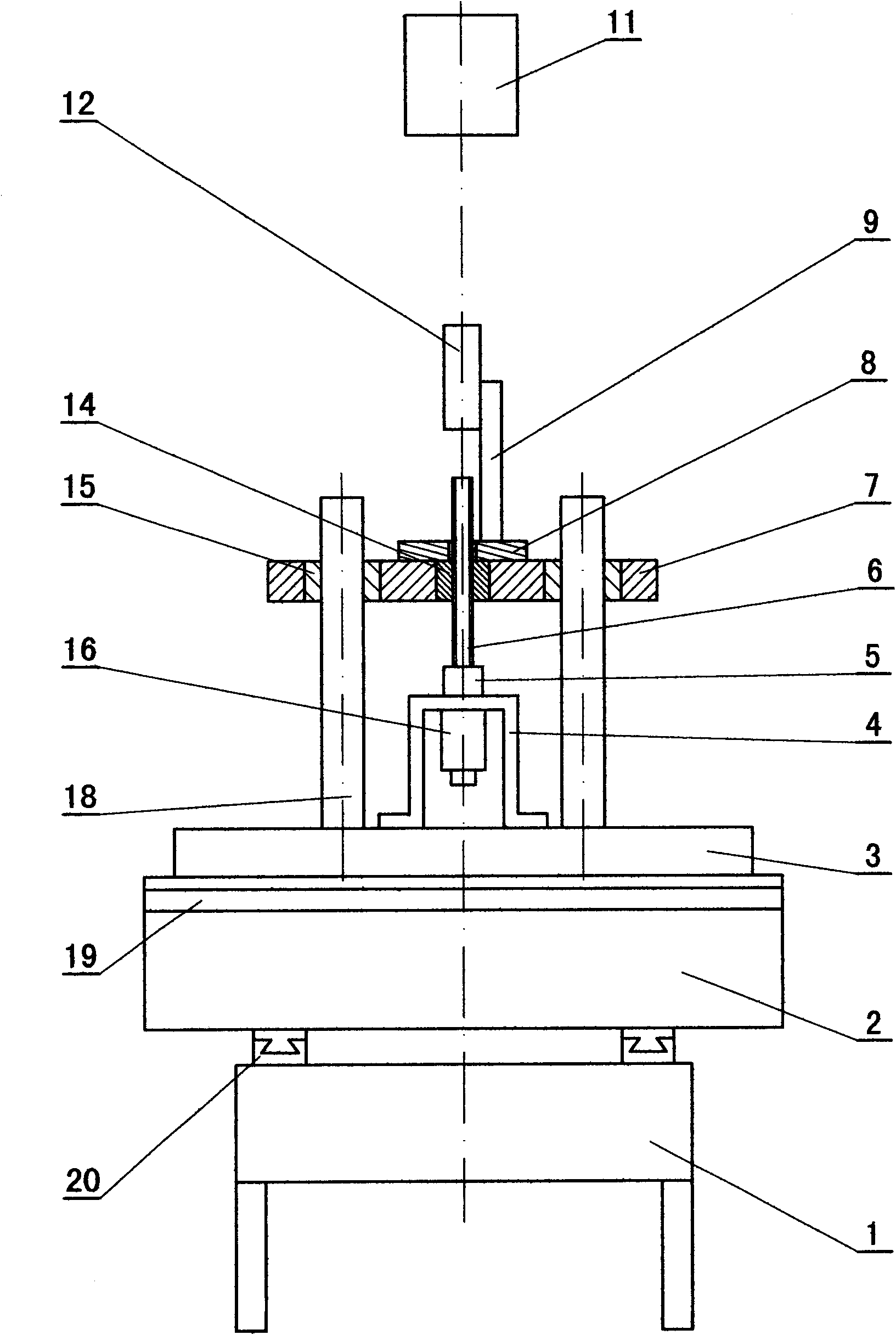
[0132] combine figure 1 ,Be explained. right first figure 1 The labels in are explained: 1 is the lower layer of the workbench; 2 is the middle layer of the workbench; 3 is the mounting plate; 4 is the connecting bracket; 5 is the connecting piece; 6 is the screw; 7 is the top plate; 8 is the support; 9 is the laser sensor 11 is a workpiece; 12 is a laser sensor; 14 is a nut; 15 is a guide sleeve; 16 is a Z-direction motor; 18 is a guide post; 19 is a second guide rail; 20 is a first guide rail.

[0133] In this example, from figure 1 It can be seen that some parts and mechanisms of the X-Y biaxial workbench include: the lower layer of the workbench 1, the middle layer of the workbench 2; the mounting plate 3, the first guide rail 20, and the second guide rail 19.

[0134] There is a first guide rail 20 between the lower layer 1 of the workbench and the middle layer 2 of the workbench; there is a second guide rail 19 between the middle layer 2 of the workbench and the mount...

Embodiment 2

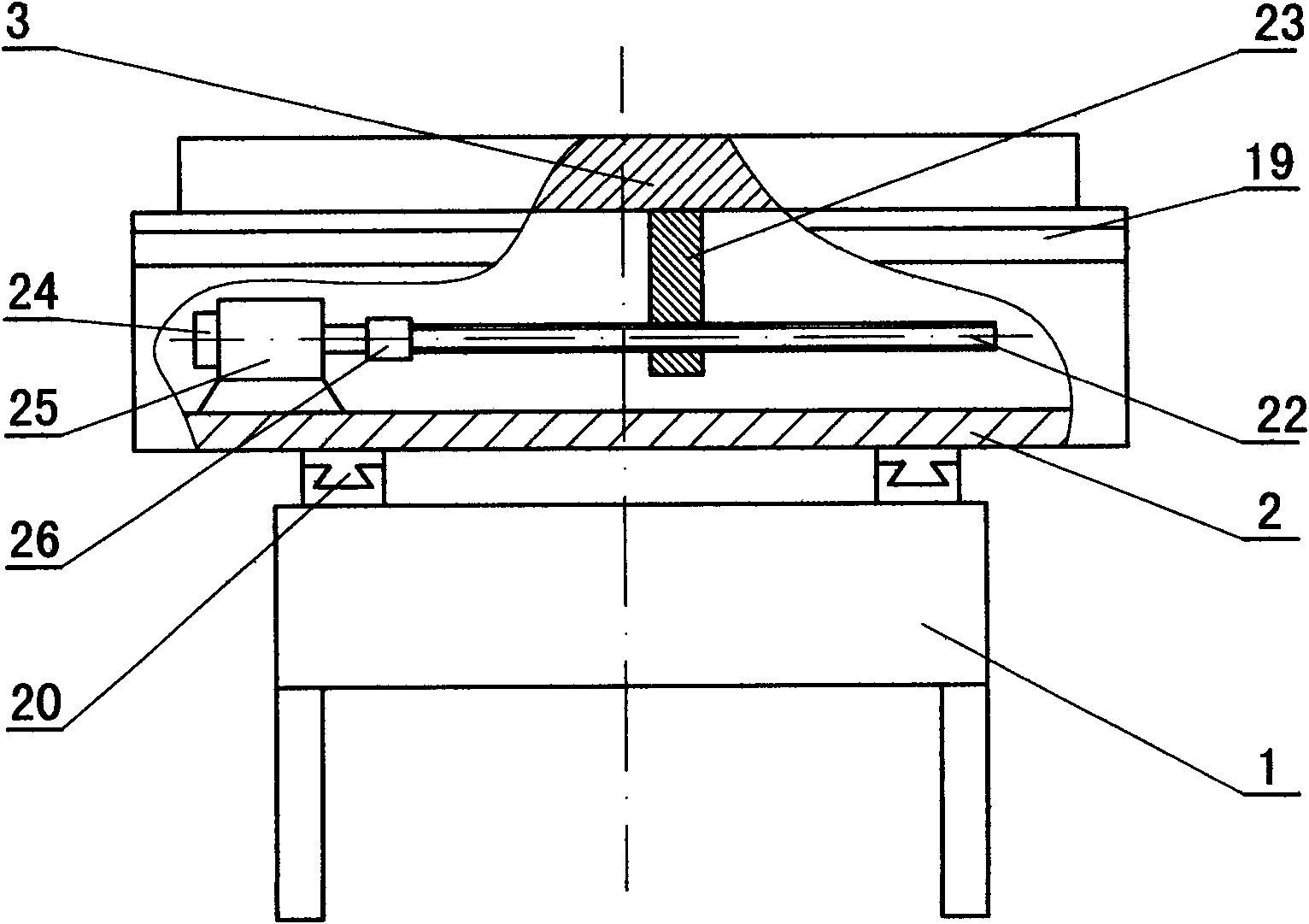
[0151] This embodiment is to give an example to illustrate a specific X-Y biaxial workbench situation. combine figure 2 , image 3 Be explained. figure 2 is the front view of this embodiment, image 3 yes figure 2 left view of .

[0152] Firstly, explain the labels in the figure: 1 is the lower layer of the workbench; 2 is the middle layer of the workbench; 3 is the mounting plate; 20 is the first guide rail; 22 is the second rotating shaft; Encoder; 25 is the second servo motor; 26 is the second connecting part; 27 is the first rotating shaft; 28 is the first supporting seat; 29 is the first encoder; 30 is the first servo motor; 31 is the first connection Component.

[0153] In this embodiment, both servomotors are connected to the output control terminals of the automation circuit through encoders and wires; and the automation circuit contains a computer.

[0154] In the X-Y double-axis workbench of this embodiment, there are two kinematic systems, one is the syste...

Embodiment 3

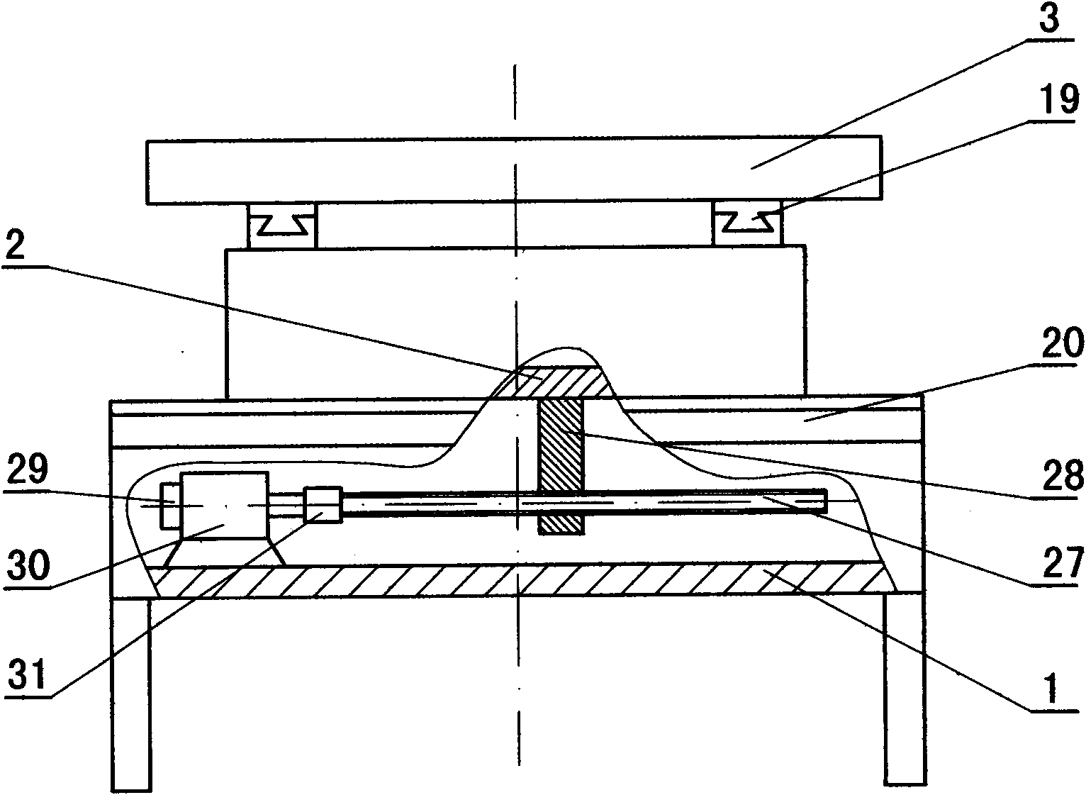
[0160] Below, combine Figure 4 Be explained. Firstly, explain the labels in the figure: 1 is the lower layer of the workbench; 2 is the middle layer of the workbench; 3 is the installation plate; 19 is the second guide rail; 20 is the first guide rail; 27 is the first rotating shaft; 28 is the first support Seat; 29 is the first encoder; 30 is the first servo motor; 32 is the front gear; 33 is the gear support; 34 is the last gear.

[0161] Such as Figure 4 As shown, the gear bracket 33 is fixedly connected with the lower layer of the workbench, the front gear 32 is fixedly connected with the output shaft of the first servo motor 30, and the last gear 34 is not only connected in rotation with the gear bracket 33, but also fixed with one end of the first rotating shaft 27 connect.

[0162] When the automation circuit sends commands to the first servo motor 30 through the first encoder 29, the following series of actions take place successively: the first servo motor 30 rot...


PUM


Abstract

The present invention provides a laser scanning location device. To solve problem of stereotactic location, the present invention provides a technical scheme that the laser scanning location device comprises a X-Y double-shaft workbench, etc., the down part of a guide pillar fixedly connects with an installing plate, the guide pillar locates in a guide sleeve, both sides slidably connect each other; the guide sleeve fixedly connects with a top plate; a Z-directional motor fixedly connects with the installing plate through a connection rack; an output shaft of the Z-directional motor connects with the down part of a screw through a connecting piece, the upper part of the screw locates in a nut; the nut and a laser sensor also fixedly connect with the top plate, an output control terminal ofan automation circuit connects with a terminal of the laser sensor and a terminal of the Z-directional motor respectively. The invention has beneficial effects in that: the laser scanning location device solves problem of stereotactic location, has high location precision, rapid motion and little electro-optical, etc.

Description

technical field [0001] The invention relates to a production equipment of a low-voltage circuit breaker, in particular to a laser scanning positioning device. Background technique [0002] With the advancement of science, the development of technology, and the increasing level of automated production, the unit cost of large-scale production of the assembly line is significantly reduced; at the same time, scientific and technological personnel are required to continuously solve many specific technologies in the process of industrial automated production. question. [0003] In the manufacturing process of the low-voltage circuit breaker, it is necessary to find the center of the workpiece in the dynamic state, that is, to determine the exact position of the workpiece. For example, when using a manipulator to process and produce a workpiece, it is first necessary to find the workpiece accurately; for another example, in the process of producing a low-voltage circuit breaker, i...

Claims


Application Information

Patent Timeline
IPC IPC(8): H01H69/00H01H11/00
Inventor 范狄庆程武山张敏良王明衍施海峰司海立董林
Owner SHANGHAI UNIV OF ENG SCI
Why Eureka
Try Eureka