Multifrequency antenna

A multi-frequency antenna and antenna technology, which can be applied to antennas, resonant antennas, electrical short antennas, etc., can solve problems such as difficult implementation, and achieve the effects of small size, light weight, and small backward radiation.

Active Publication Date: 2010-03-24
QIDONG DONGLAI ROLLING SALLSCREW
View PDF0 Cites 8 Cited by
  • Summary
  • Abstract
  • Description
  • Claims
  • Application Information

AI Technical Summary

Problems solved by technology

The ever-shrinking space poses a huge challenge to the improvement of antenna performance, especially the requirement for bandwidth is still very high. At present, there are many methods for PIFA to increase bandwidth, such as adding parasitic patches, opening rectangular grooves, and changing feed points. Structure, adding multi-layer patches or multiple branches, etc. Among them, changing the feed point structure is the most direct and effective method, but this method is not easy to realize in actual design

Method used


Image

  • Multifrequency antenna
  • Multifrequency antenna
  • Multifrequency antenna

Examples


Embodiment Construction

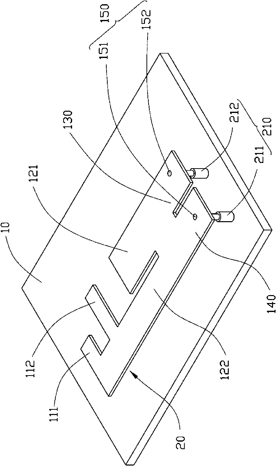
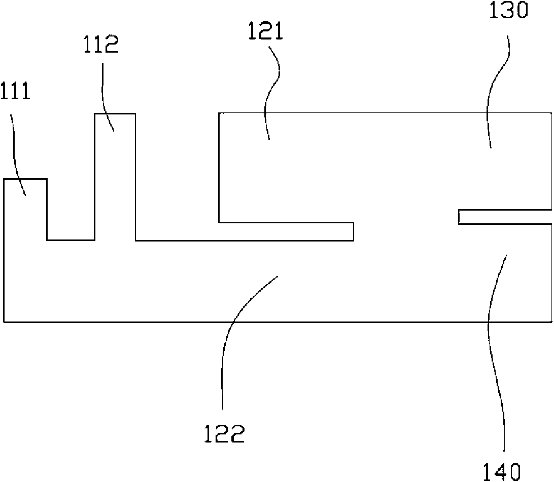
[0012] Please refer to figure 1 , which is a schematic diagram of an embodiment of the multi-frequency antenna 20 of the present invention. figure 2 It is a top view of an embodiment of the multi-frequency antenna 20 of the present invention. In this embodiment, the multi-frequency antenna 20 is disposed on the substrate 10 , and includes an elastic probe 210 , a feeding portion 130 , a grounding portion 140 and an antenna body. The feeding part 130 is used for feeding electromagnetic wave signals. The antenna body is electrically connected to the feeding part 130 and the grounding part 140 for sending and receiving electromagnetic wave signals, and includes a first resonator 111 , a second resonator 112 , a first radiator 121 and a second radiator 122 .

[0013] In this embodiment, the multi-frequency antenna 20 is connected to the elastic probe 210 through the probe point 150 , and then connected to the substrate 10 through the elastic probe 210 . The elastic probe 210 i...


PUM


Abstract

A multifrequency antenna is provided on a substrate. The antenna includes a plurality of flexible probes, a feed-in portion, a grounding portion and an antenna body. The feed-in portion is connected to the substrate for feed-in of electromagnetic wave signals. The grounding portion is connected to the substrate. The antenna body is in electric connection with the feed-in portion and the groundingportion, for transmitting and receiving electromagnetic wave signals. The antenna body includes a first radiation body, a second radiation body, a first resonance body and a second resonance body. The first radiation body is connected to the feed-in portion. The second radiation body is connected to the first radiation body and grounding portion. The first resonance body is connected to the second radiation body. The second resonance body is connected to the second radiation body, the first resonance body and the second resonance body are parallel and have unequal lengths. The inventive multifrequency antenna utilizes resonance bodies with unequal lengths to realize covering of a plurality of 2.4 and 5.X frequency bands.

Description

technical field [0001] The invention relates to an antenna, in particular to a multi-frequency antenna. Background technique [0002] The rapid development of modern wireless communication puts forward higher and higher requirements for the design of wireless communication equipment, and the miniaturization of mobile communication products has become a trend. So far, mobile communication products have achieved a high degree of integrated circuit (Integrated Circuit, IC) integration, which effectively promotes the miniaturization and low cost of mobile communication products. As for the antenna part, due to the further high requirements for shape and radio frequency performance, unprecedented challenges are also presented to designers. It can meet the requirements of beautiful shape, and also meet the bandwidth and efficiency indicators. [0003] The built-in antenna has become the first choice for the antenna design of mobile communication products due to its advantages of ...

Claims


Application Information

Patent Timeline
Patent Type & Authority Applications(China)
IPC IPC(8): H01Q1/36H01Q9/04H01Q5/00H01Q21/30H01R4/48H01Q5/371
CPCH01Q1/38H01Q9/0421H01Q5/0058H01Q5/371
Inventor 徐茂修
Owner QIDONG DONGLAI ROLLING SALLSCREW
Why Eureka
Try Eureka